In this tutorial, we will learn how to use the ADC Peripheral of the ESP8266 SoC and read some analog values. For demonstration of this ESP8266 ADC Tutorial, I will be using the ESP8266 NodeMCU board, which is based on ESP-12E Module. ESP-01 doesn’t have an ADC Pin.
Analog to Digital Converter and SoC
Analog to Digital Converter or simply ADC is an amazing feature of most modern Microcontrollers and SoCs. An Analog to Digital Converter, as the name suggests, converts continuous Analog signals in to discrete Digital Values.
This is really important as all Microcontrollers are digital devices and work only on logic LOW and logic HIGH values. ADCs allow Microcontrollers and SoCs to interface with Analog devices (like Sensors) and build systems around them.
Most modern microcontrollers already have an ADC Block built into their silicon so, you don’t need to use an external (and dedicated) ADC IC.
ADC in ESP8266 SoC
The ESP8266EX SoC, which is the main processor in all the ESP8266 Boards, has a single channel ADC. The ADC in ESP8266 has a 10-bit resolution and is of Successive Approximation Register (SAR) type. The 10-bit resolution means, the output values will be in the range of 0 to 1023.
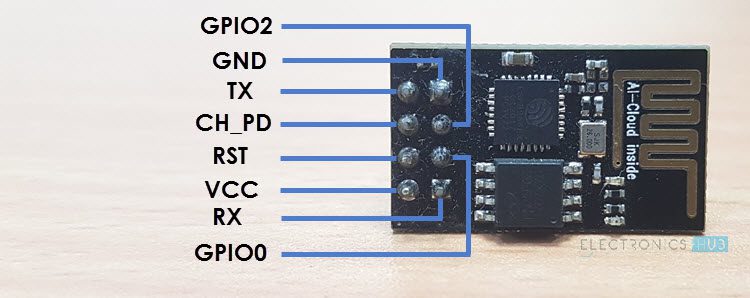
If you refer to the datasheet of ESp8266EX SoC, the ADC Pin is the Pin 6, also known as TOUT pin. The ADC can be used for basically two types of measurements. They are:
- Measure the Power Supply Voltage at Pin 3 and Pin 4.
- Measure the input voltage of Pin 6 i.e., TOUT Pin.
Both these measurements cannot be implemented at the same time. For Power Supply Voltage measurement, the TOUT Pin must be left floating. But when measuring external voltage at TOUT Pin, the input voltage range should be between 0V and 1V.
If you are building the firmware from the SDK, then refer to the datasheet and other relevant documentation, as there is a lot more information regarding the ADC and its configuration.
ADC in ESP-01
If you have the vanilla ESP8266 Board i.e., ESP-01, then you are out of luck, as it doesn’t have the pin for ADC on the board. If you are desperate, then you can use the Pin 6 as ADC Pin but remember that it can accept voltages in the range of 0V to 1V only.
ADC in ESP8266 NodeMCU
The NodeMCU board, which is essentially based on the ESP-12E Wi-Fi Module, has a pin for ADC called A0.
Additionally, NodeMCU also takes care of the input voltage range limit from the original 0V to 1V to more user friendly 0V to 3.3V.
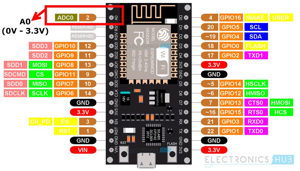
If you take a look at the schematic of NodeMCU, the ADC0 pin in the above pinout image acts as an input to the voltage divider formed by 220 KΩ and 100 KΩ resistors with the output of the voltage divider given to the TOUT Pin of ESP8266EX SoC.
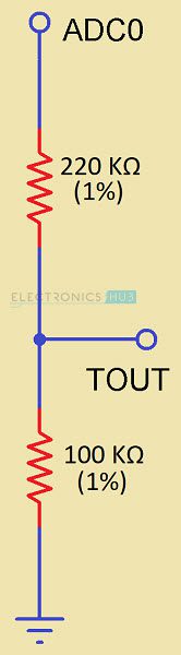
IMPORTANT NOTE: The voltage range of ADC in ESP8266 SoC is 0V to 1V. If you want to use the ADC for 0V to 3.3V, then you have to use a voltage divider circuit as shown above. ESP-01 users, who don’t have access to ADC Pin can solder a wire to Pin 6 of ESP8266EX SoC and use it with the voltage divider.
WARNING: Do not provide more than 1V directly to the ADC Pin (TOUT – Pin 6) of ESP8266EX SoC.
Demonstration of ESP8266 ADC using NodeMCU
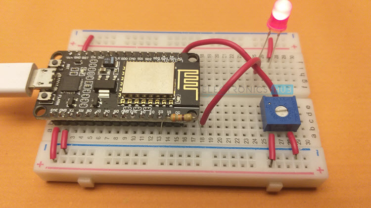
If you have an ESP8266 NodeMCU board, then you can directly use the ADC Pin (A0) for reading analog voltages in the range of 0V to 3.3V. Let us now build a small circuit to demonstrate the ADC function of ESP8266.
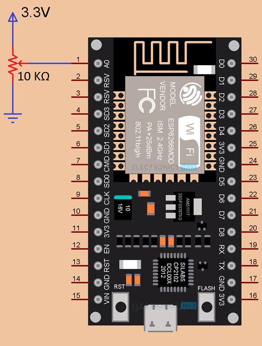
A 10 KΩ Potentiometer is chosen as the analog input device with its end terminals connected to 3.3V and GND and the Wiper Terminal connected to A0 Pin of NodeMCU. The analog voltage is converted to digital values and displayed on the Serial Monitor.

Components Required
- ESP8266 NodeMCU Board
- 10 KΩ Potentiometer
- Breadboard
- Connecting Wires
Circuit Diagram
The following image shows the circuit diagram for ESP8266 NodeMCU ADC Demonstration.
Code
Before proceeding with code, I strongly recommend you to go through the Getting Started with NodeMCU tutorial, as it has all the necessary information for setting up Arduino IDE to use with NodeMCU Board.
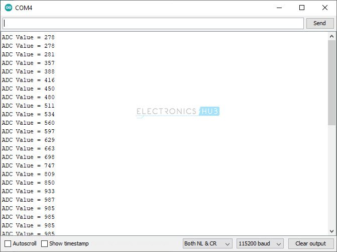
Output
The following image shows the ADC Value displayed on the Serial Monitor.
ESP8266 PWM with ADC
As an extension to ESP8266 ADC Tutorial and ESP8266 PWM Tutorial, we will now combine both the ADC and PWM features of ESP8266EX SoC and control the brightness of an LED using a Potentiometer.
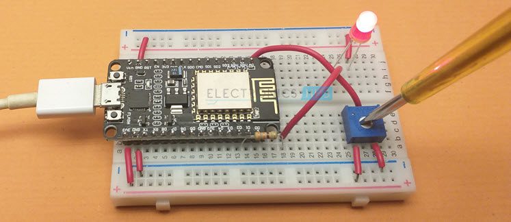
The LED is connected to GPIO4 (D2) Pin of NodeMCU and a 10 KΩ Potentiometer is connected to the ADC0 Pin of NodeMCU. As I turn the knob of the 10 KΩ POT, the brightness of the LED varies from maximum (full intensity) to minimum (LED off).
I made a dedicated tutorial on ESP8266 PWM using ESP-01 Module. Check it out for more information.
IMPORTANT NOTE: The resolution of ADC of ESP8266 is 10-bit. This means, the output of ADC will be in the range of 0 to 1023. Now, the resolution of PWM of ESP8266 is also 10-bit i.e., it can accept duty cycle values between 0 (0% duty cycle) to 1023 (100% duty cycle).
Components Required
- ESP8266 NodeMCU
- 5mm LED
- 330 Ω Resistor
- 10 KΩ Potentiometer
- Breadboard
- Connecting Wires
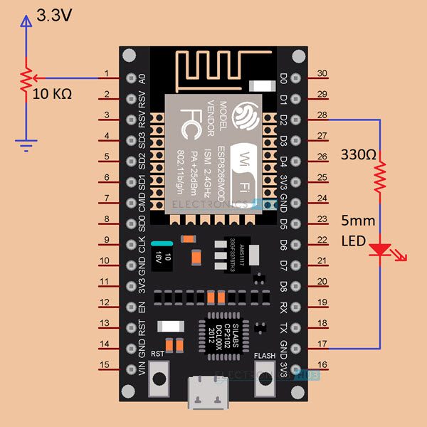
Circuit Diagram
The following image shows the circuit diagram and all the necessary connections for PWM LED Brightness Control using Analog Input from POT and ADC of ESP8266 NodeMCU.
Code
If you slightly modify the previous ADC demonstration code, you can generate a PWM signal based on the input from ADC. The output of the ADC is fed as Duty Cycle input to PWM Signal generation using analogWrite() function.
Conclusion
A simple tutorial on ESP8266 ADC Function using NodeMCU board. You learned about some of the important specifications of ADC in ESP8266EX SoC, the input voltage ranges for ADC, how to use a voltage divider to extend the input voltage range, demonstration of ESP8266 ADC with output values printed on Serial Monitor and also controlling brightness of LED using PWM.
