In this tutorial, we will learn about the ADC Peripheral in ESP32. The Analog to Digital Converter or simply ADC od ESP32 is very useful to measure analog voltages from different sensors (like LM 35 Temperature Sensor), potentiometers (for adjusting brightness of LED), etc. Learn how to use ESP32 ADC Peripheral by understanding its characteristics, pins, functions and also couple of demonstration circuits.
A Brief Note on ESP32 ADC Peripheral
The ESP32 SoC consists of two Successive Approximation Register (SAR) type Analog to Digital Converters (ADC). Together, the two SAR ADCs i.e., ADC1 and ADC2 in ESP32 consists of 18 channels. ADC1 consists of 8 channels and ADC2 consists of 10 channels.
ADC in ESP32 have a maximum resolution of ADC of 12-bits and yes, the resolution of ADC is configurable with possible values include 9-bit, 10-bit, 11-bit and 12-bit. Usually, the resolution is set to 12-bit, if not changed.
So, by default, the output of the ESP32 ADC will be a value in the range of 0 and 4095 (as the default resolution is 12-bit, the output digital values can have 212 = 4096 values). Also, the ADC input voltage limit is 3.3V i.e., ESP32 ADC can measure analog voltage in the range of 0V to 3.3V.
ADC Pins of ESP32
Unlike some of the digital peripherals (PWM, software SPI and I2C), the ADC pins are fixed i.e., you have to use the predefined GPIO Pins which have ADC functionality and you cannot configure it in software. However, there are some limitations you have to know of.
Even though ESP32 has 18 channels ADC, all the ADC pins are not available for the user. Of the 8 ADC1 channels, only 6 are available (ACD1_CH0 and ACD1_CH3 to ACD1_CH7) while ADC1_CH1 and ADC1_CH2 are not available (even the pins are not exposed in the ESP32 Development Board).
Coming to ADC2, it is somewhat complicated. When you are using the Wi-Fi of ESP32, the Wi-Fi Driver uses the ADC2 Peripheral. So, you can use ADC2 only if the Wi-Fi driver is not started.
Even when you are using ADC2 (assuming Wi-Fi is not used), all the pins are not readily available as some of the pins associated with ADC2 are used for other important purpose (Boot Strapping).
The following table shows the ADC Channels, Arduino style names (A0, A1, etc.), GPIO Pins and any important points to remember.
|
ADC Channel |
Pin Name | GPIO Pin |
Notes |
|
ACD1_CH0 |
A0 | GPIO 36 | Free to use / Hall Sensor Pin |
| ACD1_CH1 | GPIO 37 |
Not available |
|
|
ACD1_CH2 |
GPIO 38 | Not available | |
| ACD1_CH3 | A3 | GPIO 39 |
Free to use / Hall Sensor Pin |
|
ACD1_CH4 |
A4 | GPIO 32 | Free to use |
| ACD1_CH5 | A5 | GPIO 33 |
Free to use |
|
ACD1_CH6 |
A6 | GPIO 34 | Free to use |
| ACD1_CH7 | A7 | GPIO 35 |
Free to use |
|
ACD2_CH0 |
A10 | GPIO 4 | |
| ACD2_CH1 | A11 | GPIO 0 |
Used as BOOT Pin / Not available |
|
ACD2_CH2 |
A12 | GPIO 2 | Used as BOOT Strapping Pin |
| ACD2_CH3 | A13 | GPIO 15 |
Used as BOOT Strapping Pin |
|
ACD2_CH4 |
A14 | GPIO 13 | |
| ACD2_CH5 | A15 | GPIO 12 |
|
|
ACD2_CH6 |
A16 | GPIO 14 | |
| ACD2_CH7 | A17 |
GPIO 27 |
|
|
ACD2_CH8 |
A18 | GPIO 25 | |
| ACD2_CH9 | A19 | GPIO 26 |
|
By taking account of all the information mentioned above, it is a safe bet that the 6 available ADC1 pins (ACD1_CH0 and ACD1_CH3 to ACD1_CH7) can be used without any ambiguity.
ADC1_CH0 and ADC1_CH3 are also associated with Hall Effect Sensor.
Other ESP32 Development Boards may have their own restrictions. So, definitely check for the datasheet and schematic and check if a particular ADC pin is free to use or not.
ADC Functions
There are nine function exposed by the ADC driver. They are:
- analogRead(pin): Get the ADC Value for the specified pin.
- analogReadResolution(bits): Set the resolution of output of analogRead. Default is 12-bit but possible values are 9 to 12.
- analogSetWidth(bits): Sets the sample bits and read resolution. Default is 12-bit but range is 9 to 12.
- analogSetClockDiv(clockDiv): Set the divider for the ADC clock.
- analogSetAttenuation(attenuation): Set the attenuation for all channels. Default is 11db but possible values are 0db, 2_5db, 6db, and 11db.
- analogSetPinAttenuation(pin, attenuation): Set the attenuation for a particular pin.
- adcAttachPin(pin): Attach pin to ADC (done automatically in analogRead).
- analogSetVRefPin(pin): Set pin to use for ADC calibration if ESP32 is not already calibrated. Possible pins are 25, 26 or 27.
- analogReadMilliVolts(pin): Get millivolts value for pin.
Measure Analog Voltage
With the theory, pin information and library functions laid out, we can now start to develop circuits to actually use the ADC Peripheral of ESP32. For the first project, let us see how to configure the ADC channel of ESP32 and measure an analog voltage applied to one of the ADC Pins.[ESP32 Projects for Beginners]
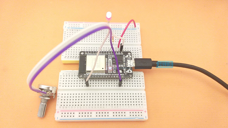
The simplest way to provide variable analog voltage is with the help of a Potentiometer. Connect the ends of POT to 3.3V and GND of ESP32 Development Board and connect the Wiper to any of the ADC Pin. To keep things simple, I used the ADC1_CH0 i.e., GPIO 36 (A0) as the ADC Pin.
Components Required
- ESP32 DevKit Development Board
- 10 KΩ Potentiometer
- Breadboard
- Connecting Wires
- 5mm LED
- 220Ω Resistor
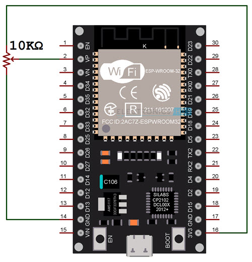
Circuit Diagram
The following image shows the circuit diagram for measuring analog voltage using ADC of ESP32.
Code
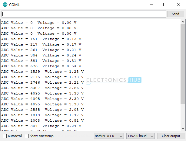
The code is very straight forward if you ever worked with ADC of Arduino or ESP8266. Read the ADC value of the ADC Pin (A0 in this case) using ‘analogRead’ function, convert the digital value into voltage using a small calculation and display the result on Serial Monitor.
The output of the Serial Monitor looks something like this:
LED PWM using ESP32 ADC
I made a dedicated tutorial on the working of LEDC PWM in ESP32. Read that tutorial for in-depth understanding of PWM in ESP32. We can set the duty cycle of the PWM output of ESP32 using ADC.
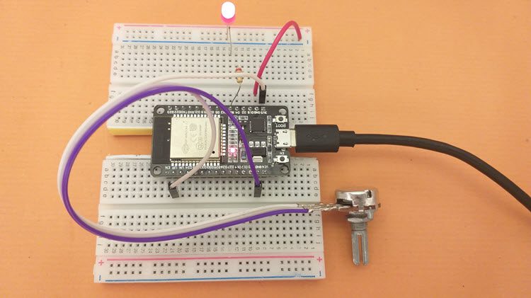
The ADC Pin is the same as earlier i.e. A0 (ADC1_CH0 – GPIO 36) and the PWM Pin is GPIO 16. I connected a 5mm Red LED to this pin using a 220Ω current limiting resistor.
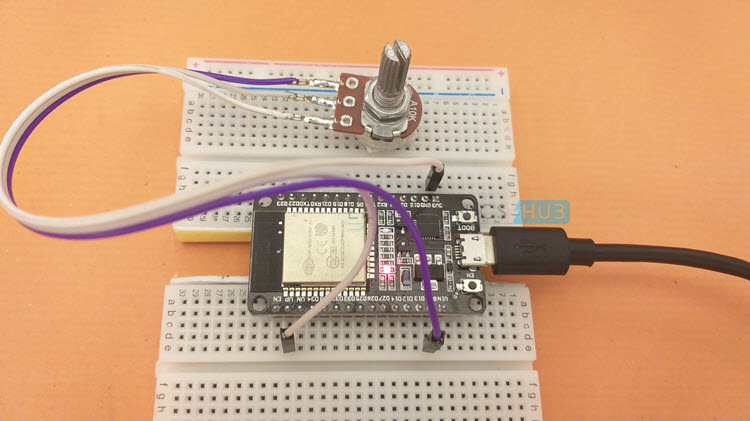
Circuit Diagram
The following image shows the circuit diagram for manually configuring the duty cycle of PWM using ADC of ESP32 and thus adjusting the brightness of an LED.

Code
Conclusion
A complete tutorial on using ADC Module in ESP32. You learned about the ESP32 ADC Peripheral, its associated pins, what ADC pins are safe to use, how to measure analog voltage using ADC in ESP32 and also how to manually adjust the brightness of an LED using ADC and PWM in ESP32.

One Response
Very nice article, however for myself I would like to see more info of the high speed capture abilities of the ESP32. In my case I require the CPU to capture 4 simultaneous analog pulses that have a duration from 10 to 50 milliseconds with a resolution of 20 scans per millisecond on each of the 4 analog inputs. I have seen notes in the Espressif data sheet that claims the analog inputs are capable of really high speeds (i.e. 2Msps for the DIG controller) but nowhere is it explained in detail.