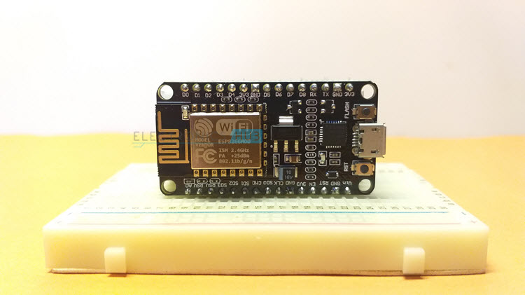
In this tutorial, we will learn some basic Digital Input and Digital Output operations on ESP8266. I chose the NodeMCU board for demonstrating ESP8266 NodeMCU Input Output operations using LED as a Digital Output device and a Push Button as a Digital Input Device.
Configure GPIO Pins On ESP8266 NodeMCU for Input/Output
This is just a beginner’s guide for understanding how to configure the GPIO Pins of ESP8266 NodeMCU board as Digital Input and Digital Output.
Before proceeding with this tutorial, I strongly recommend you to go through the “Getting Started with NodeMCU” and also the “NodeMCU Pinout” tutorials, as I discussed some of the basic yet very important topics related to ESP8266 NodeMCU Board.
In the Getting Started with NodeMCU tutorial, I talked about how to setup Arduino IDE for programming NodeMCU board. This step is very important and it is a one-time job i.e., setup your Arduino IDE properly and you don’t have to worry again and again.
Coming to the NodeMCU Pinout tutorial, I spoke about all the important information regarding the pins of ESP8266 NodeMCU board. This is also an important tutorial as you will understand what pins can be used as GPIOs and what pins are used for other purposes (like UART TX and RX or SPI Flash etc.).
After going through both these tutorials, it is time to test the ESP8266 NodeMCU Input Output operations. A simple 5mm LED with a current limiting resistor is used as an Output Device to test the Digital Output function while a Push Button with Pull-Down Resistor is used as an Input Device to test the Digital Input function.
So, let’s get started.
ESP8266 NodeMCU Input Output Operations
If you looked at the ESP8266 NodeMCU Pinout, you will realize that not all the GPIO Pins of the NodeMCU Board can be used as simple GPIO Pins foe Digital Input and Output operations.
Out of the 17 GPIO Pins, 8 are already used for other operations like UART, SPI Flash. So, you are left with 9 GPIO Pins. Even in that 9, some of them are used while Boot up process while some have a default state at the time of boot up.
So, you have to be extremely careful in selecting the right GPIO Pins. For example, if you select a GPIO Pin to drive a Relay and if its state at boot is HIGH, then the relay will be turned on during the boot up. This situation may or may not be useful for all the applications.
As a safe bet, I used GPIO4 and GPIO5 i.e., D2 and D1 on NodeMCU for demonstrating this project. These pins do not have any alternate functions and can be used freely without any doubt.
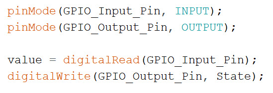
To configure a GPIO pin either as Input or Output, you have to use the pinMode() function. Once the pins is setup, you can read from an input pin using digitalRead() function and write to an output pin using digitalWrite() function.
Components Required
- ESP8266 NodeMCU
- 5mm LED
- Micro USB Cable
- 330 Ω Resistor
- 10 KΩ Resistor
- Push Button
- Breadboard
- Breadboard Power Supply (optional)
- Connecting Wires
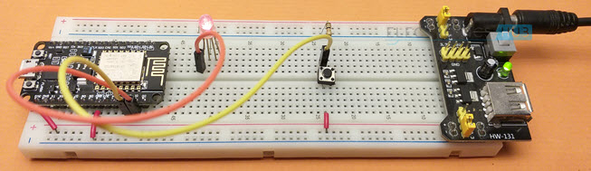
Circuit Diagram
The following image shows the circuit diagram for demonstration of ESP8266 NodeMCU Input Output Operations.

Code
The code for the project is given below. You don’t have to download any additional libraries.
Working
This is a simple project, where you press a button and the state of the LED will toggle i.e., if it was LOW previously, it will become HIGH and vice-versa. Now, let us go through the code and understand it’s working.
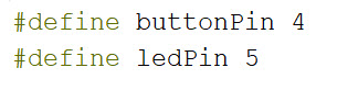
Initially, we define the pin numbers for LED and Push Button. I used “#define” macros but you can also use “const int” variables. GPIO5 or D1 is used for LED and GPIO4 or D2 is used for Push Button.
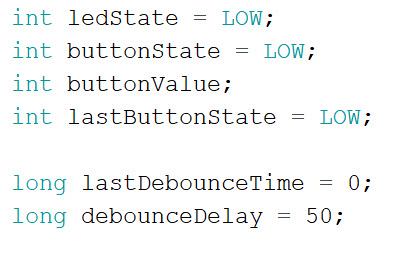
Then, I declared some variables to hold the status of the LED and Push Button (both current state and previous state of the button and the current state of the LED). Also, there are couple of variables for Button Debounce implementation.
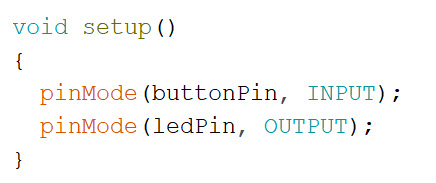
In the setup() function, you initialize the “ledPin” and output and the “buttonPin” as input using the pinMode() function with appropriate arguments (OUTPUT and INPUT respectively).
Coming to the loop() function, in the first line, you read the state of the button pin using digitalRead() function and store the value into buttonValue variable.

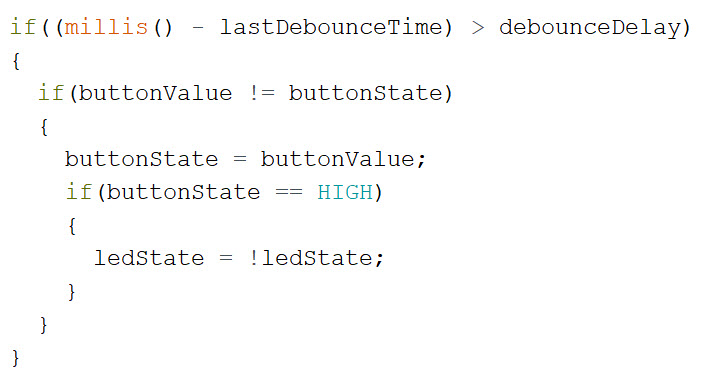
Next is the button debounce part of the code. Wait until the debounce delay is passed since the button is pressed and then use the button state value acquired previously. This will eliminate accidental presses and noise.

If the button state has changed and if it is equal to HIGH, then only toggle the state of the LED.
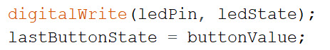
Finally, apply the new state of the LED using digitalWrite() function and also store the current state of the button.
Sample Output Video
The following gif is a small video snippet of the output.
Conclusion
A simple tutorial to understand the ESP8266 NodeMCU Input Output operations of the GPIO Pins. You learned how to setup a GPIO Pin of NodeMCU as either an Input or as an Output.
