Pulse Width Modulation or PWM is a technique of delivering power to loads like LEDs and Motors (PWM can also be used to encode messages). In this ESP8266 PWM Tutorial, I’ll teach you how to use ESP8266 WiFi Module to generate Pulse Width Modulation (PWM) signals that will be used for LED Fading.
Overview
We have seen several PWM tutorials using a variety of microcontrollers (or IC’s) like 8051, Arduino, Raspberry Pi and IC 555. Using the PWM technique, we have controlled the intensity of an LED (increased or decreased its brightness), changed the speed of a DC Motor (increase or decrease the speed) and also rotated a Servo Motor.
Now in this ESP8266 PWM Tutorial, I will control the brightness of an LED connected to the GPIO2 Pin of the ESP8266 WiFi Module i.e. LED Fading using ESP8266.
PWM in ESP8266
The ESP8266EX Microcontroller i.e. the SoC that is the heart of all the ESP8266 Modules (like ESP-01, NodeMCU, etc.) consists of four dedicated PWM output interfaces. The pins corresponding to PWM in ESP8266EX are as follows:
|
PWM Pins in ESP8266EX |
|
|
Pin Name |
Pin Number |
|
MTDI |
10 |
|
MTDO |
13 |
|
MTMS |
9 |
|
GPIO4 |
16 |
If you observe, all these four pins are not available in our ESP8266 ESP-01 WiFi Module. Then how can we implement PWM in ESP8266?
The answer for this is very simple: using Software Programming i.e. using Timers of the microcontroller, to be exact.
PWM in ESP8266 WiFi Module can be implemented with the help of Timer Interrupts. The frequency of the PWM signal can be anywhere between 1Hz to 1KHz (some say, the minimum frequency is 100Hz!).
How to Implement PWM in ESP8266?
The software implementation of the PWM generation in ESP8266 is very similar to that in Arduino. Since we are using the Arduino IDE to program the ESP8266, the function responsible for producing PWM Signal is analogWrite (the same function which we have used in Arduino as well).
analogWrite function takes in two parameters: Pin number and PWM Value. In place of Pin Number, enter the number of the Pin through which you want use the PWM Output.
Coming to the PWM Value, here you need to enter a value based on the resolution of the PWM. In case of Arduino, the resolution is 8-bit, so you would have to enter a value between 0 and 255.
In case of ESP8266, the PWM in ESP8266 uses a 10-bit resolution. So, you will have to enter a value between 0 and 1023. Here, PWM value “0” means 0% duty cycle and PWM value “1023” means 100% duty cycle. Any value between 0 and 1023 will make the duty cycle.
NOTE:
- If a pin in ESP8266 has been assigned analogWrite to generate PWM Signal, it cannot be used as a digital output pin i.e. you cannot use digitalWrite(); function on that pin.
- In order to use the pin as a digital pin, you need to write analogWrite(pin number, 0) in order to free it up.
Circuit Diagram of ESP8266 PWM Tutorial for LED Fading
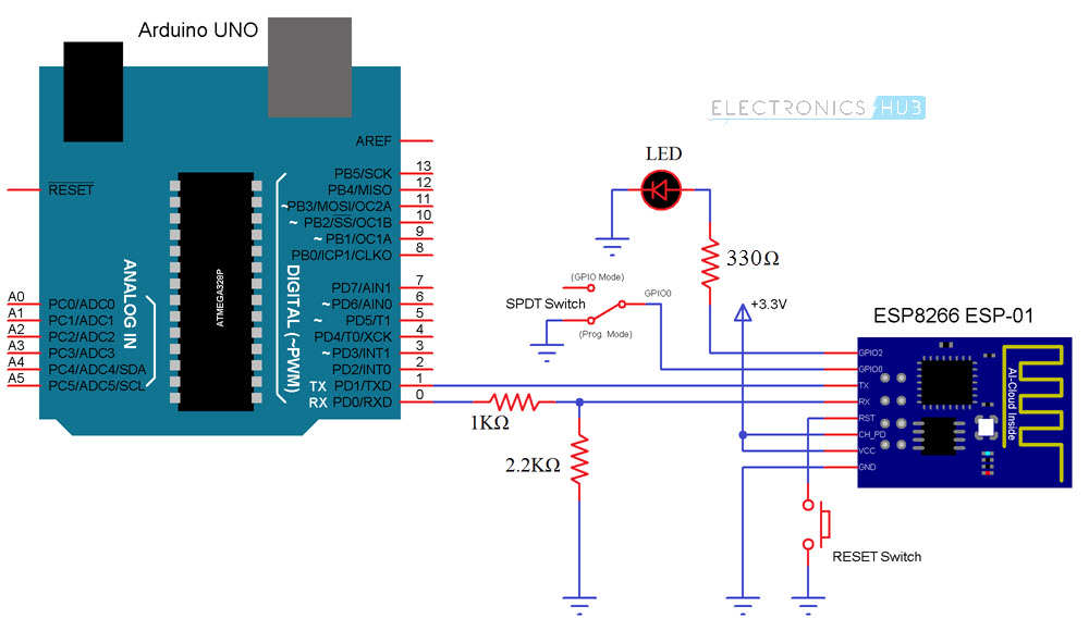
The following image is the circuit diagram for programming ESP8266 WiFi Module using Arduino as USB-to-Serial Converter and also LED Fading using PWM Signal.
Components Required
- ESP8266 WiFi Module (ESP-01)
- Arduino UNO
- Push Button
- SPDT Switch (Slide Switch)
- Resistors (1 KΩ and 2.2 KΩ)
- Small LED (5mm or 3mm)
- Connecting Wires
- Breadboard
Circuit Design
Connect an LED (I have used an 8mm LED, you can use a 5mm or 3mm LED with a current limiting resistor) to the GPIO2 pin of the ESP8266 WiFi Module.
The VCC and CH_PD are connected to a 3.3V supply and GND is connected to GND. RST (Reset) pin of the ESP8266 WiFi Module is connected to GND through a push button.
Now, the RX and TX pins of the ESP8266 are connected to RX and TX of Arduino UNO. Note in the circuit diagram that the RX pin of ESP8266 is not directly connected to the RX pin of the Arduino but through a level converter (consisting of 1KΩ and 2.2KΩ Resistors).
Finally, the GPIO0 Pin. This pin responsible for enabling programming mode in the ESP8266. Connect the GPIO0 Pin to a SPDT slide switch i.e. to its centre terminal and connect one of the two terminals to GND. The other terminal is used as a GPIO Pin.
Code
The code for ESP8266 PWM LED Fading Tutorial is given below.
Working
After making all the connections properly as per the circuit diagram, enable Programming Mode in ESP8266 i.e. slide the GPIO0 switch to GND position and push the RST button.
Upload the code using Arduino IDE (first, select Generic ESP8266 Module in boards and also the correct PORT Number).
After uploading the program, slide the GPIO0 pin to GPIO Position and push RST button once. Now, the code will start running and initially you can see the LED slowly increasing its brightness through 5 steps to maximum intensity.
After this, the fading action begins where the LED fades in and out i.e. low to high and high to low is a loop.
Applications
- The ESP8266 PWM Tutorial is just a demonstration of the PWM function of the ESP8266 WiFi Module.
- Using the PWM Technique in ESP8266, you can implement several projects like Servo Motor Control, Web Controlled Servo, DC Motor Speed Control etc.

One Response
I want about .. what is an arduino and how it’s works