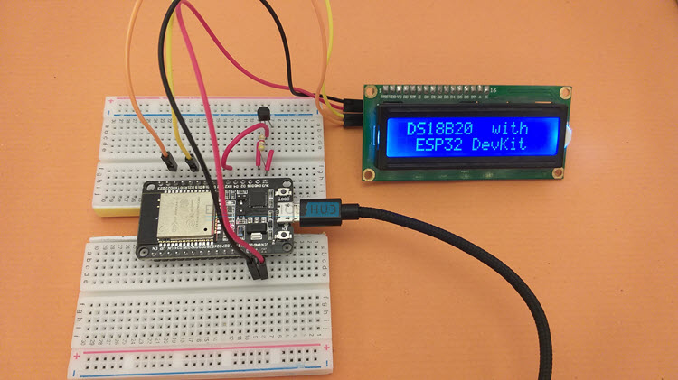
In this tutorial, we will learn how to interface DS18B20 with ESP32 DevKit Development Board. If you want to build a Web based Temperature Monitoring System using ESP32, then DS18B20 is an excellent choice for the Temperature Sensor. Learn how ESP32 DS18B20 Temperature Sensor interface works, setup Arduino IDE, display the temperature on an LCD. Additionally, you can design a simple ESP32 Web Server which continuously displays the temperature.
A Brief Note on DS18B20 Temperature Sensor
We already used DS18B20 Temperature Sensor in a couple of earlier projects involving Arduino, Raspberry Pi and ESP8266. DS18B20 is a digital Temperature Sensor from Maxim Integrated, which can measure temperatures in the range of -550C to +1250C.[ESP32 Projects for Beginners]
Unlike other digital sensors, which often communicate over I2C or SPI, the DS18B20 Temperature Sensor uses 1-Wire Communication to interact with a Microcontroller.

If you are not familiar with 1-Wire bus, it is a communication bus developed by Dallas Semiconductor, and as the name suggests, it requires only one wire to communicate with a Processor (well, 1 Data Line and 1 GND Wire).
Additionally, the DS18B20 Temperature Sensor can derive its power from the data wire itself (known as Parasite Power), without the need for providing any external power (through the VDD Pin).
Since the DS18B20 is a Digital Temperature Sensor, the temperature data is stored in the on-chip EEPROM. Some of the other important features of DS18B20 are:
- User configurable resolution between 9-bits and 12-bits.
- A 64-bit Serial Code which is unique to each DS18B20 Sensor.
Pin Diagram and Pin Description of DS18B20
The following image shows the Pin Diagram and the table next shows the pin description of DS18B20.
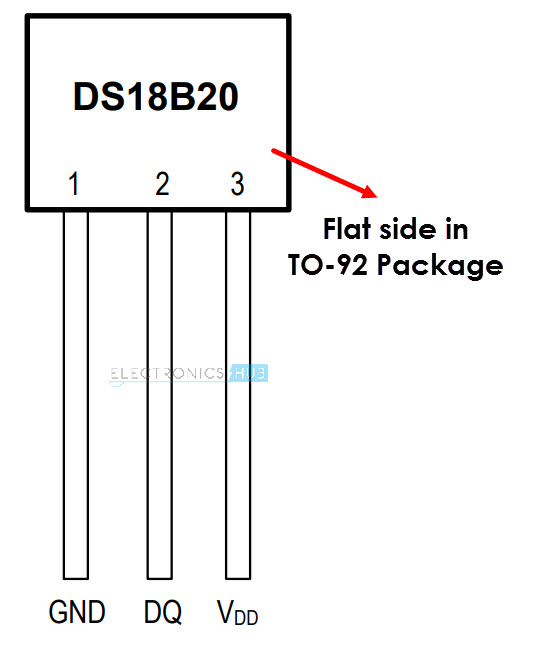
| Pin of DS18B20 | Description |
| GND | Ground |
| DQ | Input / Output Data. Must be pulled HIGH. |
| VDD | Power Supply |
Different Ways to Power DS18B20
I already discussed this in the Arduino DS18B20 Tutorial. There are a couple of ways in which you can power up DS18B20:
- Normal Way (using VDD)
- Parasite Power
Refer to Arduino DS18B20 Tutorial for more information. I will power up DS18B20 normally in this ESP32 DS18B20 Tutorial.
ESP32 DS18B20 Interface
Now that we have seen a little bit about DS18B20, let us now proceed with understanding how to interface DS18B20 with ESP32. First thing to remember is that DS18B20 is a Digital Sensor. The next important thing to remember is it uses 1-Wire Communication.
What does this mean for ESP32? This means we can use any Digital GPIO Pin of ESP32 to send and receive data to / from DS18B20 and we need only one wire for proper communication.
Components Required
- ESP32 DevKit Development Board
- DS18B20 Temperature Sensor
- 16×2 LCD
- PCF8574 I2C LCD Module
- Breadboard
- Connecting Wires
- Micro USB Cable
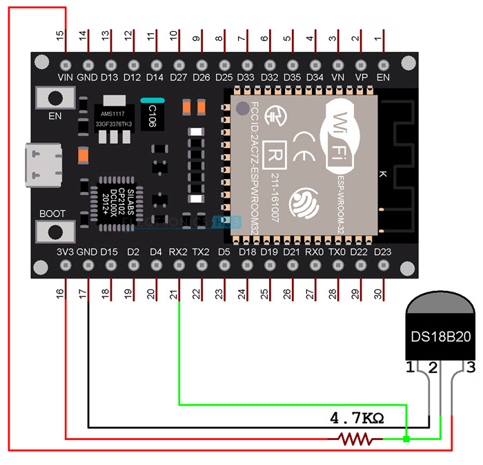
Circuit Diagram
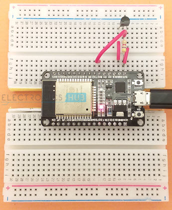
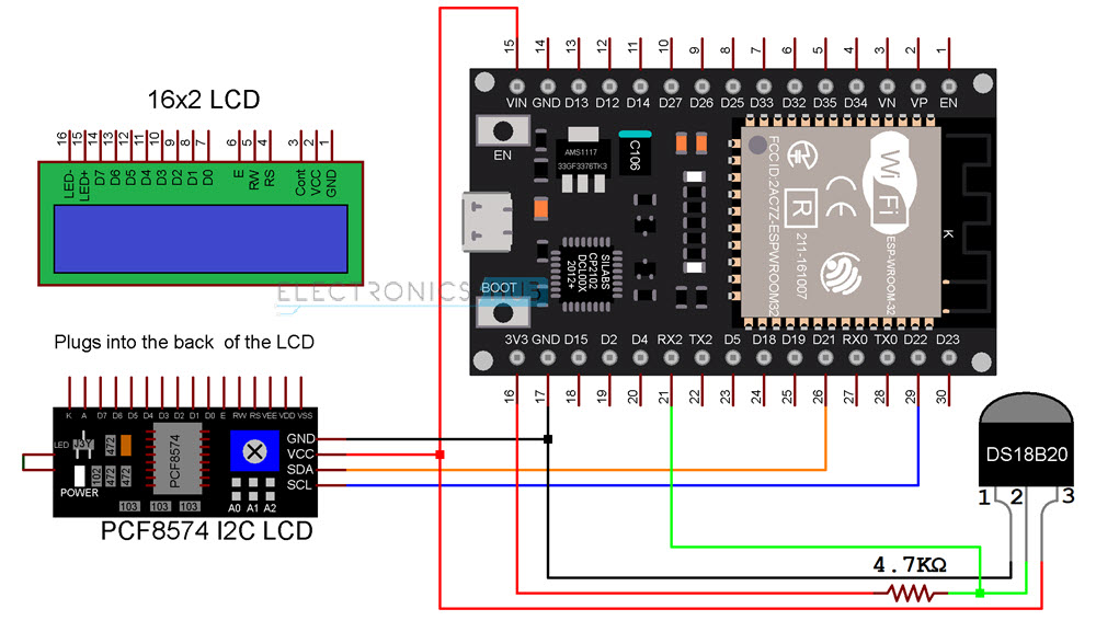
The following image shows the connections between ESP32 and DS18B20. First of all, I am powering DS18B20 with normal power. So, the VDD of DS18B20 is connected to VIN of ESP32 Board.
NOTE: The range of power supply for DS18B20 is from 3 V to 5.5 V. So, you can power DS18B20 with a 3.3V Supply from ESP32 Board as well.
Next, the GND pin is connected to any GND pin of ESP32. Finally, the DQ Pin. First of all, this pin should be pulled HIGH. So, I connected a 4.7 KΩ Resistor between DQ Pin and 3.3V.
NOTE: The pullup voltage can be anywhere between 3 V to 5.5 V.
Now, the DQ pin is connected to GPIO 16 of ESP32, which is labelled as RX2 on the ESP32 DevKit Board.
Preparing Arduino IDE
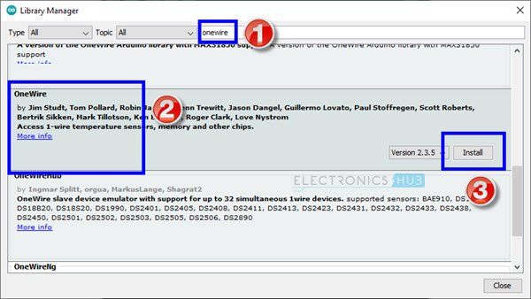
There are couple of libraries you need to download to properly communicate with DS18B20. First is related to the 1-Wire Bus. Go to Tools -> Manage Libraries… in Arduino IDE.
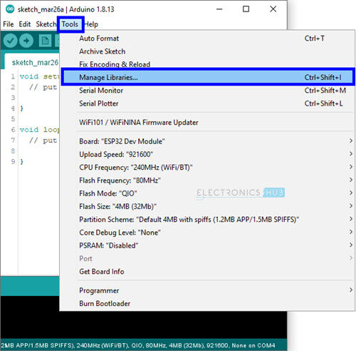
In the search bar, enter ‘onewire’. Scroll through the options and install ‘OneWire’ library by Jim Studt, Paul Stoffregan Et Al.
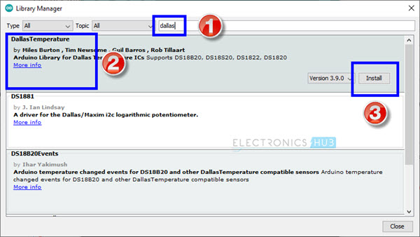
The next library is associated with the DS18B20 device itself. Search for ‘dallas’ and install ‘DallasTemperature’ by Miles Burton Et Al.
Displaying Temperature on Serial Monitor
After making the proper connections and installing the necessary libraries as mentioned above, we will now see how to read the temperature data from DS18B20 using ESP32 and display the result on the Serial Monitor.
Code
I wrote a simple code which will initialize the 1-Wire Communication on GPIO 16, assign this One Wire Communication to the DS18B20 Sensor and reads the temperature data.
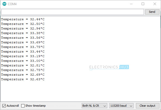
To view the result, I simply used the serial monitor to print the temperature values in degree Celsius.
The following image shows the screenshot of the Serial Monitor, which is continuously printing the temperature reading every 3 seconds.
ESP32 DS18B20 with I2C LCD
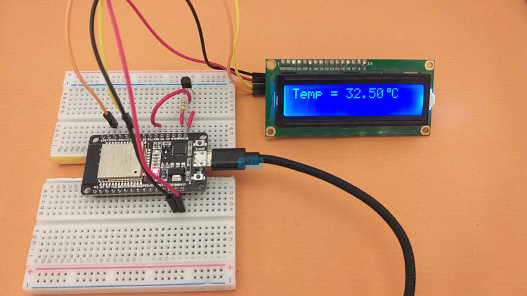
Displaying temperature values on Serial Monitor is useful just for testing the connections and the code itself. If you want a more practical “Embedded System” application, then using a display module of any kind (OLED, 16×2 Character LCD, Nokia 5110 LCD, graphical LCD etc.) to view the temperature reading is the simplest approach.
To keep things simple, I used a regular 16×2 Character LCD Display Module in combination with PCF8574 I2C LCD Module to display the temperature readings from ESP32 DS18B20 Interface.
I made a dedicated tutorial on how to use an I2C LCD with ESP32. Check out that tutorial for in-depth information. I also discussed the necessary libraries you have download to successfully connects I2C LCD with ESP32 in that tutorial.
NOTE: I also explained how to get the Slave Address of I2C LCD Module in that tutorial. This step is very important.
Circuit Diagram
The additional components you require are a 16×2 LCD Display and an I2C LCD Module (based on PCF8574). Plug-in the I2C LCD Module at the back of the 16×2 LCD Display. The I2C LCD Module needs only four connections (two of them are for power and two are for data).
All the necessary connections between ESP32 and I2C LCD Module as well as between ESP32 and DS18B20 Temperature Sensor are shown in the following circuit diagram.
Code
The code for ESP32 DS18B20 Interface with I2C LCD is very simple. The initialization part of the sensor is similar to the previous code. Only the LCD related code is additionally added.
Conclusion
A beginner’s tutorial on interfacing DS18B20 Temperature Sensor with ESP32 is implemented here. You learned some basic information about DS18B20, how ESP32 DS18B20 Interface works, necessary libraries for communicating with DS18B20, how to display temperature on Serial Output and also how to connect I2C LCD with ESP32 and display the temperature readings.
As far as a Web based Temperature Monitoring System using ESP32 and DS18B20 is considered, I will update this page shortly with the code for Web Server.

One Response
Dear friend,
in the sketch above it shouldn’t be “#define DS18B20PIN 21”?
Best,
Helio.