In general, magnetostatic fields are produced by the motion of electric charges with uniform velocity whereas electrostatic fields are produced by the stationary charges. On the other hand, electromagnetic fields are the time varying fields that are produced by time varying currents.
These fields cause to generate emf based on electromagnetic induction principle. In 1831, The English physicist Michael Faraday and the American scientist Joseph Henry simultaneously and independently discovered that any change in a magnetic field of a coil of wire will cause to induce an emf or voltage in that coil.
Such phenomenon of generating emf from magnetic field is called electromagnetic induction. Two familiar applications of this principle are electric generator or alternator which is the source of electric power and the transformer which increase or decrease the emf of an AC circuit.
What is Electromagnetic Induction?
The phenomenon or method of getting an induced emf in a conductor through cutting the flux lines by the conductor is called electromagnetic induction.The electromotive force, emf is not force as the name says, but it is the work per unit charge done by the force.
It has the dimensions of energy per charge. This emf can be generated in two ways which obtained from Faraday’s experiments, namely stationary coil, moving magnet and stationary magnet, moving coil. Let us understand these two in brief.
Stationary Coil and Moving Magnet
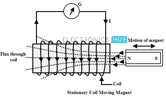
In this method, a coil of N turns kept constant and the permanent magnet which produces the magnetic lines is moved relative to the coil. Consider the below figure in which a coil having N turns is connected to the galvanometer which gives the indication of current in the circuit.
A permanent magnet is moved in such that the magnetic lines through the coil get changed. So the galvanometer stats deflecting whenever there is a motion of permanent magnet. More will be the galvanometer deflection when the permanent magnet is moved more quickly.
The reason for this current flow is the generation of emf by the movement of flux lines with respect the stationary coil. This emf drives the current flow through the circuit.
Stationary Magnet and Moving Coil
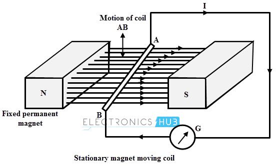
This is another form of obtaining EMF by moving a coil in the magnetic field produced by the stationary magnet. The below figure shows an arrangement that consists a coil AB, which is moved by some external means and it is connected to a galvanometer to indicate the current flow.
Whenever AB conductor is moved either upward or downward, there is cutting of the flux lines by the conductor. Hence an emf is induced in the conductor and current starts flowing through the circuit thereby galvanometer starts deflecting.
The direction of the current flow is determined by the movement of the conductor in the magnetic field. More will be the current flow if the conductor is moved quickly.
From the above two methods, it is to be noted that to have induced emf, there must be a change in magnetic flux lines with respect to the conductor. The necessary elements to have this induced emf are a conductor or coil, a magnetic field (electromagnet or permanent magnet) and relative motion between the magnetic flux and the conductor.
Faraday’s laws of Electromagnetic Induction
As given above, two scientists discovered the electromagnetic induction namely Michael Faraday and Joseph Henry. Since Michael Faraday has published his finding first and investigated in more detail about electromagnetic induction, the law that describes the electromagnetic induction is named after him. He stated two laws of electromagnetic induction.
Faraday’s First Law
It states that whenever the magnetic lines of force (magnetic flux) linked with a closed circuit changes or alternatively whenever a conductor cuts or is cut by the magnetic flux, an emf is induced in the circuit which results to the flow of induced current through the circuit. As long as the magnetic flux changes or relative motion persist between conductor and magnetic flux, this emf is induced.
Faraday’s Second Law
It states that the magnitude of the emf induced in a circuit or coil is directly proportional to rate of change of flux linkages.
Consider a coil having N turns and the initial flux linking as Φ1. Thus the initial flux linkages associated with the coil is N Φ1. During the time t, the flux linking with the coil changes from Φ1 to Φ2. Then the final flux linkage of the coil is N Φ2.
Therefore the rate of change of flux linkages = (N Φ2 – N Φ1) /t
According to Faraday’s law, an emf would be generated in the coil due to the change of flux linkages, and as per the second law, this emf is proportional to the rate of change of flux linkages. i.e.,
e α (N Φ2 – N Φ1) /t
e = (N Φ2 – N Φ1) /t
e = N dΦ /dt
Where dΦ /dt is rate of change of flux
N is the number of turns of the coil
This induced emf produces the current in such a direction that it opposes the very cause of its producing it according to the Lenz’s law. This opposition is represented by a negative sign mathematically as
e = – N dΦ /dt ……………….(1)
The induced emf is a scalar quantity that is measured in volts. It can be written in terms of electric field as
e = ∮Ē.(dL̄) ………….(2)
The above equation voltage about a closed path such that if any part of the path is changed, the emf induced will be changed.
The total magnetic flux passing through a specified area in terms of magnetic field is given as
Φ = ∮s B̄.(ds)̄
WhereB is the magnetic flux density
Then the equation 2 becomes (assuming that N=1 i.e., single turn coil)
e = – d /dt (∮sB̄.(ds)̄)……………(3)
∮E ̅ .(dL) ̅ = – d /dt (∮sB̄.(ds)̄ ) ………….(4)
This is called as integral form of the Lenz’s law.
By considering the equation 4 and applying Stroke’s theorem, we get
∮s ∇ ×Ē.(ds)̄) = – d /dt (∮sB̄.(ds̄ )
If the circuit is stationary, the time derivative can be moved inside the integral then it becomes a partial derivative as
∮s ∇ ×Ē.(ds)̄) = – ∮(s )(∂ /∂t ( BM.(ds)M))
Then equating the integrals
∇ × EM = ∂/∂t BM
This is called as differential form of Faraday’s law.
Lenz’s law
This law is named after the German Physicist Heinrich Lenz, who derived it. This law states that the direction of the induced emf produced by electromagnetic induction always such that it tend to set up a current that oppose the cause which is responsible for producing it.
Here the cause is a change of flux that is responsible for producing the emf. So the induced emf always opposes the cause of producing it and it is represented by a negative sign in the mathematical expression of emf.
e = – N dΦ /dt
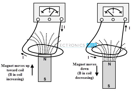
Consider the below figure in which coil is connected to a galvanometer. Let a bar magnet is moved towards the coil. This movement of the magnet induces an emf in the coil, thereby generating the current. According to the Lenz’s law the direction of the induced current is in such a way that it opposes the motion of the magnet as shown in figure.
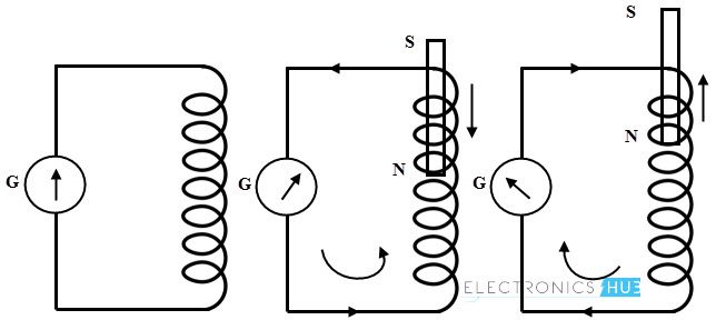
The current induced due to the emf generates its own magnetic field which opposes the main field which causes to generate the emf. So the Lenz’s state that the current induced around a closed loop is such that a magnetic field produced by it tries to counteract the change in magnetic flux which causes to generate emf.
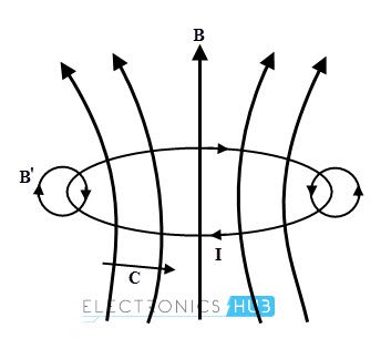
In below figure, the closed loop current flows in clockwise direction due to the induced emf. In accordance with the Lenz’s law, if the magnetic field B is increasing then the circulating current generates a field B’ which opposes the increasing in magnetic flux B through the loop.
Then the emf induced over a closed loop becomes,
∮C EM.(dl)M ) = – d /dt (∮sBM.(ds)M )
Where negative sign represents the Lenz’s law
Inductance
The magnetic induction effect in a coil when the inside magnetic field changes with time is represented by the inductance L. The cause for producing an emf in a coil is current flowing through it. So any change in the current in a coil is opposed by the induced emf in accordance with Lenz’s law.
This property of opposing the change in current is called as inductance. Such a change of flux inside the coil takes place not only due to the change in current in the coil, but also the change in currents in nearby coils. Hence the inductance can be self inductance or mutual inductance.
Self Inductance
Suppose a given circuit a single loop coil, then any change in current changes the magnetic flux associated with the current. The given coil itself intercepts the flux and change in flux would result to induce the emf in the coil itself. This emf is called self induced emf which drives the induced current opposite to the change in current.
This means when the current is increased then induced emf reduces the current and tries to keep its original value. Similarly, if the current is decreased, the induced emf increases the current and tries to maintain original value.
Hence any change in current through the coil is opposed by the coil and this property is called as the self inductance of the coil. Since the induced emf opposes the cause for its production this emf is also called as back emf or counter emf.
If the circuit has N identical turns, then the flux linkage is equal to the NΦ. And also if the medium surrounded by the circuit is linear then the flux linkage is directly proportional to the current. i.e.,
The total flux linkage, λ = NΦ and
λ α NΦ
λ α I
λ = L I
Where L is the constant known as inductance
L = λ / I
L = NΦ / I
Alternatively
e = – N dΦ /dt
The flux can be expressed as
Φ = (Φ / I) × I
As long as the medium is linear (permeability is constant), the ratio of flux to the current is constant.
Rate of change of flux = (Φ / I) × Rate of change of current
dΦ/ dt = (Φ / I) × dI/ dt
Substituting in emf equation, we get
e = – N (Φ / I) × dI/ dt
e = – (N Φ / I) × dI/ dt
Where (N Φ / I) is the self inductance and is denoted as L. It is defined as the flux linkages per ampere current and measured in Henry (H). Then
e = – L dI/ dt
Further this coefficient of self inductance is expressed as
L = NΦ / I
But Φ = mmf/ reluctance
= NI/S
Then L = (N / I) × (NI/S)
L = (N2 / S)
Also Reluctane S = l/µa
Where l is the length of the magnetic flux path and a is the area of the cross section of magnetic circuit through which magnetic is passing.
Then L = (N2 / (l/µa))
L = (N2 µ a / l)
L = (N2 µo µr a) / l Henries
Mutual Inductance
The phenomenon of generating induced emf in a circuit by changing the current in other neighbouring circuit is called mutual induction. Consider that two coils which are placed adjacent to each other as shown in figure. The current through the coil A produces the flux Φ1 and part of this flux is linked with coil B.
This is called as mutual flux Φ2. If the current through the coil A is changed, then the flux Φ1 also changes. Since this flux is associated with coil B, the change of mutual flux Φ2 induces emf in the coil B. This emf is called as mutual induced emf.
This emf further drives the current through the coil B. Hence the mutual inductance is the property by which emf gets induced in the coil due to the change in current in another coil.

The emf induced in the coil B is
e2 = – N2 dΦ2 /dt
The negative sign represents that the induced emf set up a current that opposes the change of flux linking with the coil according to the Lenz’s law.
We can express Φ2 = (Φ2/I1) × I1
If the permeability of the medium is constant, Φ2 is proportional to the I1 and hence the ratio (Φ2/I1) is constant.
Rate of change of Φ2 = (Φ2 / I1) × Rate of change of current I1
dΦ2/ dt = (Φ2 / I1) × dI1/ dt
Therefore the emf induced is
e2 = – N2 (Φ2 / I1) × dI1/ dt
e2 = – (N2 Φ2/ I1) × dI1/ dt
In the above equation (N2 Φ2 / I1) is the mutual inductance and is denoted as M. It is defined as the total flux linkages in a coil per ampere current change in other coil. And it is measured in Henries (H). Then emf induced is
e2 = – M × dI1/ dt
Further, this mutual inductance is expressed as
M = (N2 Φ2 / I1)
Where Φ2 is the part of the flux Φ1 produced due to I1. Consider that K1 is the fraction of Φ1 which is linking with coil B, i.e,
Φ2 = K1 Φ1
Then M = (N2 K1 Φ1 / I1)
The flux Φ1is expressed as
Φ1 = mmf / Reluctance
= (N1 I1) / S)
Therefore, M = (N2 K1 / I1) × (N1 I1) / S)
M = (K1 N1 N2) / S
If the total flux produced by the coil A links with coil B then K1= 1
M = (N1 N2) / S
But S = S = l/µa
Then M = (N1 N2) / (l/µa)
M = (N1 N2 µo µr a) / l Henries
This is the mutual inductance of the coil B with respect to the coil A. Mathematically mutual inductance of coil B due to coil A and mutual inductance of coil A due to coil B is same.
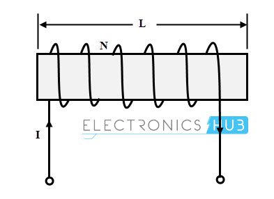
Inductance of a Solenoid
Consider a solenoid having N turns as shown in figure. And consider that the current flowing through the solenoid be I amperes, A be the the cross sectional area and l be the length of the solenoid.
The field intensity of the solenoid is given as
H = NI/ l Ampere per meter
Total flux linkage = N Φ
= N B A
= N µH A
= µ N H A
Substituting H in the above equation
Total flux linkage = µ N (NI/ l) A
= (µ N2 I A) / l
Therefore the inductance of the solenoid is given as
L = Total flux linkage /Total current
L = (µ N2 I A) / l) / I
L = µ N2 A) / l Henries
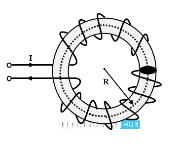
Inductance of a Toroid
Consider a toroid ring of radius R with turns N is shown in figure below. Let the current through the ring is I ampere.
The magnetic flux density inside a toroidal ring is given as
B = (µ NI) / (2πR)
Total flux linkages in a toroidal ring with N turns is given as
Total flux linkage = N Φ
= N B A (since Φ = B A)
= N ((µ NI) / (2πR)) A
= (µ N2 I A) / (2πR)
Therefore the inductance of a toroid is
L = Total flux linkage /Total current
= (µ N2 I A) / (2πR) (I)
L = (µ N2 A) / (2πR)
Wher A is the cross sectional area of the toroid which is equal to πr2 meters
For a toroid having inner radius r1 and outer radius r1,height h with total number of turns N, the inductance is given as
L = ((µ N2 h) / (2π) ) ln (r2/r1)
Examples of Application of Electromagnetic Induction
Electric Generators
An electric generator produces the electrical energy from a mechanical work (opposite function of motor which converts mechanical energy to electrical energy).
The shaft of the electric generator is rotated by some mechanical means such as a turbine or an engine, thereby emf is induced in the coil windings according to the Faraday’s laws of electromagnetic induction.
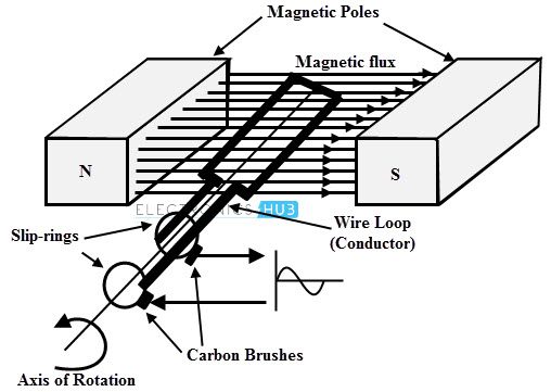
The principle operation of the electric generator is explained by a coil of wire that is rotated by uniform magnetic field as shown in above figure. But in practical generator, the wire usually wound on the iron core.
Each wire is formed as coil and the ends of the coils are connected to the external circuit by means of slip rings that rotates with the coil.
The external circuit is connected to the stationary brushes which gets contact with slip rings when each ring slides. In generators, the magnetic flux can be either moving or stationary depends on the stationary or moving conductor.
In the above figure, stationary flux is produced by the permanent magnets and the conductor or coil is moving with respect to the stationary flux. Due to the relative motion between the conductor and the flux, an emf will be induced in the coil or conductor.
This emf drives the current to the external load circuit. When the plane of the motion of the conductor is parallel with the plane of the flux the emf induced is zero and when it is perpendicular then emf induced will be maximum. This emf is also called as dynamically induced emf.
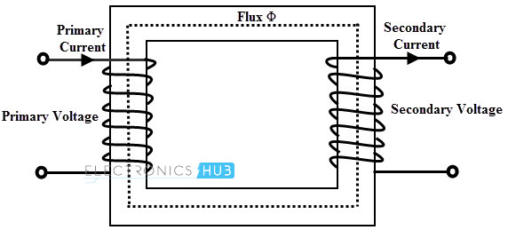
Transformer
A transformer essentially consists of two or more windings on a closed iron core. By using the transformer, the power can be transformed from one alternating current circuit to another with desired change in voltage and current levels. The transformer works based on the mutual induction principle between two coils.
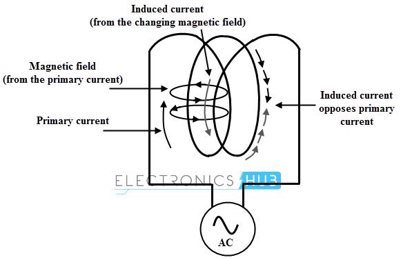
When a voltage is applied to the primary winding, a current is passes through it and set up a magnetic flux in the core. This flux induces an emf in the primary coil which must be exactly equal and opposite to applied voltage. The same flux is also linked with secondary winding on the other limb of the core.
Thus an emf is induced in the secondary winding by the electromagnetic induction principle. The emf’s associated with respective windings depends on the number of turns in each winding. Therefore, without an electrical coupling between the circuits, a transformer transfers the power from one circuit.
The desired voltage ratio from primary to secondary is obtained by properly selecting the turns ratio from secondary to primary.
Apart from these major examples, there are numerous applications that use electromagnetic induction principle for their functioning such as electric power transmission, induction cookers, industrial furnaces, medical equipments, electromagnetic flow sensors, musical instruments (like electric violin and electric guitar) and so on.

2 Responses
It is very useful to the students
This is fantastic source for knowledge