In this project, I will show you how to design a simple Robotic vehicle that can be controlled using a phone. The project is called DTMF Controlled Robot without Microcontroller.
Introduction
DTMF is an acronym for Dual Tone Modulation Frequency. Robotic vehicle based on DTMF technology is explained in this article. Here, is a circuit that operates the robot without using a microcontroller. This circuit consists of simple DTMF Tone decoder IC and a motor driver IC.

When a key is pressed from our mobile, it generates a tone, which is a combination of two frequencies. Of the two frequencies, one is high frequency and another one is low frequency. This frequency can be decoded by the decoder IC into binary sequence. Using this binary sequence, the robot is controlled.
DTMF Based Robotic Vehicle Circuit Principle
DTMF based robotic vehicle circuit consists of DTMF Decoder IC, Motor Driver IC (L293D or L298N), motors and a simple robot chassis to hold all these components.
DTMF decoder IC used is HT9170B (actually a variant called CM8870 is used but the functionality is the same). It has 18 pins. Tone from DTMF encoder is given to the DTMF decoder IC. The decoder IC internally, consists of operational amplifier, whose output is given to pre filters to separate low and high frequencies. Then it is passed to code detector circuit and it decodes the incoming tone into 4bits of binary data. This data at the output is directly given to the driver IC to drive the two motors. These motors rotate according to the decoded output.
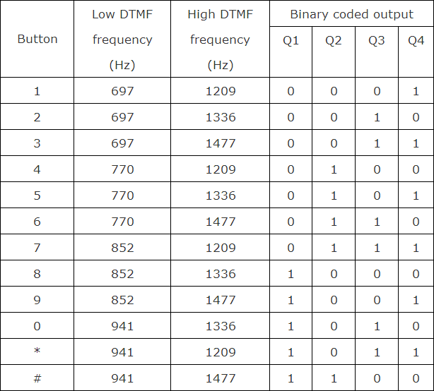
The following image shows the binary decoded output corresponding to the key pressed on the keypad.
Also Read the Related Post: Simple Line Follower Robot using Microcontroller
If the button pressed from mobile is ‘8’, it gives a decoded output of ‘1000’ (in the order of Q1, Q2, Q3 and Q4). Thus motor connected to the first two pins (OUT1 and OUT2) will rotate and the second motor stays off. So, the robot moves in one direction either to left or right. If the robot is to rotate forward or backward then the binary value should be either ‘0101’ or ‘1010’. These values indicate that two motors rotates in the same direction i.e. either forward or backward. The above table gives the low frequency, high frequency and binary output value of each button pressed in the keypad.
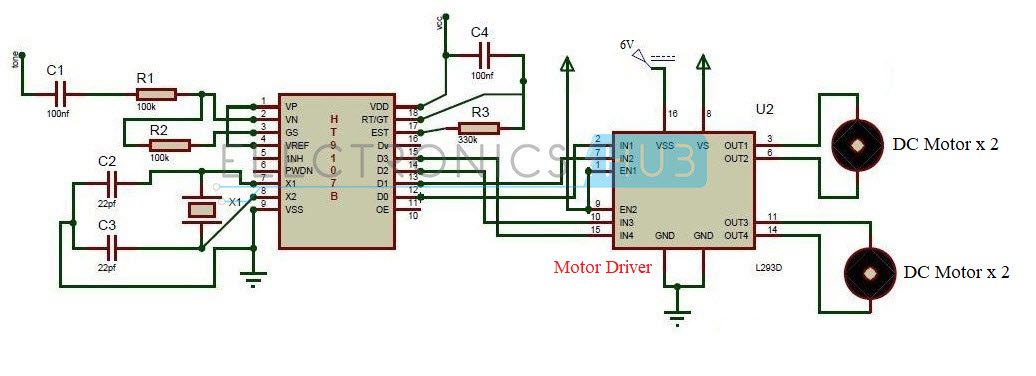
Circuit Diagram of DTMF Controlled Robot without Microcontroller
Circuit Components
- DTMF Decoder IC (HT9170B or CM8870)
- Motor Driver IC (L293D or L298N)
- Motors
- Resistors – 100KΩ x 2, 330KΩ
- Capacitors – 100nF x 2, 22pF x 2
- Crystal – 3.58MHz
- Robot Chassis
- Batteries
NOTE
- As mentioned earlier, the DTMF Decoder IC used here is CM8870. But the circuit diagram mentiones the DTMF Decoder IC as HT9170B. Since the pins are same, there won’t be any problem. But please refer to the datasheet.
- Also, the circuit diagram mentions the Motor Driver as L293D but the motor driver used here is L298N. Please refer the datasheet for pin diagram.
DTMF Controlled Robot Circuit Design
The main components of the circuit are DTMF decoder IC, motor driver IC and motors. The decoder IC used here is CM8870 IC. The second pin of decoder IC is an inverting pin of the operational amplifier.
Tone is applied to the IC through a series of capacitor and resistor. The output of the Op Amp is feed back through GS pin of the IC. An external crystal is connected to the 7th and 8th pins of the IC.
Motor driver IC used is L298N. It has 15 pins. If you are using a Module, then connect the Outputs from the decoder IC to IN1, IN2, IN3 and IN4. The motors are connected to OUT1, OUT2, and OUT3, OUT4.
Related Post: Remote Operated Spy Robot Circuit
How to operate DTMF based Robotic Vehicle?
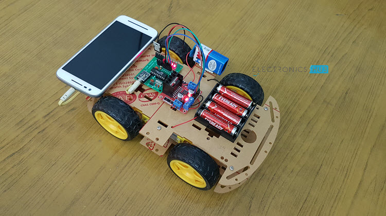
- Arrange the robot mechanically i.e. connect the wheels to the motors, place the circuit on the robot with a mobile fixed to it.
- Now press ‘5’ from your mobile, robot starts moving forward.
- Now press ‘0’ from your mobile, robot starts moving backward.
- Now press ‘2’ to rotate the robot in left direction.
- Now press ‘8’ to rotate the robot in right direction.
DTMF Controlled Robotic Vehicle Circuit Applications
- DTMF robot with slight modifications can be used in industrial applications.
- DTMF robot with human detector sensor can be used at the time of disasters like earth quake to detect the human under buildings.
- DTMF robot with camera can be used in surveillance systems.
Limitations of DTMF Controlled Robotic Vehicle
- DTMF robot may not work properly if it is operated with another mobile when there is no signal.
- Mobiles with particular jacks are only used.

87 Responses
Hello Sir,
I am currently in third year of electronics and telecommunication. For my mini project, i want to make this. can you please provide me with the necessary details like coding etc. That will be of very much help. You can send me details on my email id gauravdhangar91@gmail.com. Thank you.
here coding not required ,as it it is pre programmed, you need to give the connections according to the circuit diagram.
ok
I purchase dtmf controlled robot vechilce
Hello Sir,
I am currently in third year of electronics and telecommunication. For my mini project, i want to make this. can you please provide me with the necessary details. That will be of very much help. You can send me details on my email id madhuri143bhosale@gmail.com. Thank you.
Please go through the article.All the information for building this is project is provided in this.
sir,
can I use MT8870 IC instead if HT9107B?
please reply and thank in advance
Can some one send me crystal value
Hey Admin,
I really appreciate your project and thank you very for the detailed explanation. It helped me a lot. However, I am currently working on DTMF Controlled Robot ‘WITH’ Microcontroller. So, If you have a similar analysis, could you please share?
Also, I am looking for applications of dtmf based moving robot for industrial monitoring (using microcontroller).
Any info regarding the subject would be of great help.
Even if anybody else has any info, please mail me. Thanks in advance!
My email id: haritha.padala124@gmail.com
Hello Sir,
I am currently in third year of electronics and telecommunication. For my mini project, i want to make this. can you please provide me with the necessary schematic digram of dtmf decoder circuit,and i am also varying the speed of motor using pic4550 controller that is decoded output is given to the pic and then driver ic,so i want schematic diagram and some synopsis of the project,that will too much help me. That will be of very much help. You can send me details on my email id ajagtap8020@gmail.com. Thank you.
plz send me crystal value
3.57Mhz Crystal
13.7uF
Hello Sir,
I am currently in third year of electronics and
telecommunication. For my mini project, i want to make
this. can you please provide me with the necessary details
like coding etc. I also wants to know how it works and which components are used with their ratings and all the necessary details in brief description. That will be of very helpful for me.
You can send this information to my email id
mool.anjali5@gmail.com
Thanking you in advance.
This project does not require any coding..Please go through the article you can get all the information required
Hello Sir,
I am currently in third year of electronics and
telecommunication. For my mini project, i want to make
this. can you please provide me with the necessary details
like coding etc. And I also wants to know how it works and which components are used with their ratings and all the necessary details of this project. That will be of very helpful for me. You can send this information to my email address
mool.anjali5@gmail.com
hi ,it was a nice video, cn we implement wireless web camera? and to implement it do we require mc board
cant find HT9107B ic..any other option??
You can use MT8807D IC
Is there any change in the circuit if we use MT8807D IC
thanks in advance
Hi, i want to make this.Any one can provide me coding this project. . You can send me details on my email id saifullahsaeed617@gmail.com.i will very thankful him.
This is the project without microcontroller..You do not require any code to implement this..
hi can u tell which jack did u use , is it 3.5mm jack ??
It is 0.5mm jack
how you connected it on the circuit?
Jack is connected using two pin wire on the circuit
What is the perpose of using external crystal osc. ????
This oscillator is used to provide clock for DTMF IC
what happened if i dont use it . so that i will come to know the importance of it .. I dont know much about osc
your device will not respond according to your input commands
Hello, could you please help me out? Are those electrollitical o dielectrical capacitors!? What happens with the common wire of the tone!?
Iam currently in 2nd year of EIE any one hepl me to build this project in advance plz…
i cant see where u have used the crystal oscillator does it come inbuilt with the that IC ur using?
Crystal oscillator is used in DTMF board..
can you please send me the neccesary values of the components to
my id
charansa430@gmail.com
Please go through the circuit diagram for values of the components
to move this robot in a certain direction,do we have to keep pressing the certain button .plz plz reply me.thnx
No…once the input is received from the phone…robot will be in that state until next input is received
what if i use cm8870…??
and plzz tell me about the connections of audio jack…
for tip, ring and sleeve..
hy you applied input at inverting terminal?
Hello i am 3rd year engineering students i will implement the DTMF based robotic control without using microcontroller project using the Ckt diagram which shown in electronics hub site but i will confused what i should give to input an antenna or mobile. The video given below whose Ckt is very different than Ckt diagram. Plz help me give me full details as soon as possible.
Here audio jack is connected to the mobile…Please follow the circuit diagram for conenctions…In the video we have used PCB boards..But the circuit is same
can we use 9V battery instead of 5V ?please reply me ii have to complete this project in very short time.
thanks
There is no 5v battery in the circuit…Please be clear with your question
Yes there is 5v supply at pin no 8 of motor driver ic..
i am working on this project.i inserted leds on four inputs with resistances.but all leds are glowing even dtmf input isnt given to it.
plz guide me i have to complete project.
tthnx
This is very nice but how can we connect the mobile to the circuit????
Mobile is connected using mobile jack…Two wires(ring , tip) of the jack are connected to DTMF IC
Please sir send me the details of the components used in this project at harsh3buddy@gmail.com
thank you
WILL YOU PLEASE SEND ME THE RASTING OF COMPONENTS USED IN BOTH BOARDS SUCH AS RATINGHG OF CRYSTAL , CAPACITOR, RESISTANCE, DIODE, VOLATGE REGULATOR
can you please tell me the details of the components such as ratings of capacitor, resistance, diode used in l293d board
Dear sir,
Can we add infrared sensor nd proximity sensor in dtmf controlled robot. If yes, plz give a suggestion…
Thank you
In this project simply the direction of the robot are controlled using DTMF technology. Explain clearly about requirements of your project.So that we can help you..
Hi, we are going to make this for our project. May i know the voltage value of the 100nf and 22pf capacitors? We can’t find those valtage value in the article, thank you in advance. ?
Can any one tell tell the RPM and Frequency of the motor….plz
this is very nice.how can i get this circuit with online.
can u please tell me the website to purchase this?
Is it programming
Can we use Any coding
I want to learn how to program a microcontroller please who will teach me
mail me …. EGBULONURAYMOND@GMAIL.COM
I’m not getting the ic HT9107B can I use HT9170B ic instead of that
which frequency crystal use ? pls. reply immedieatly .
Plz tell me the use of capacitors and resistors in the circuit.It’s urgent…….
How it is work in ISIS Proteus ?
please reply immedietly
Thank You
Hi sir , how much is the cost of this circuit ? con you help me about the hardware and code of this circuit
i well select it as a final project so i need to your help
Thanks a lot
hello
i am impressed with ur project where i can fid further details of it and i nedd cost estimated for ics
i just want to extend it by heating sensor connecting to it so can u just help us
Hi I’m ece final year student, I’m thinking to do dtmf controlled robotic, send please details, cost ,
Hii i want to know the total cost of the project
Whether coding is required for the movement of robot
Hi, You do not need any programming. Just build the circuit and control the robot using your mobile phone.
hey,
you have used BO motor or geared motor? Of how much rpm and operating voltage? And what is value of crystal?
Please help.
Hi, we have used a geared motor of 150RPM and an operating voltage of 5V. The crystal used for DTMF Decoder IC is 3.579545MHz.
What type of phone jacks should it be? How do I know if the phone has the jack that I need? Thank you in advance.
3.5mm Headphone Jack would do fine.
Please provide me the details of Crystal component and project details pls….
The frequency of the Crystal Oscillator is 3.579545 MHz.
Hello, sir
Can we use l289n instead of l293d motor driver?
Sir,
I have a problem in this project the robo is not moving straitly it moving in circular so i checked the motor inputs it is not giving equal voltages to the each motor what will we do pls tell us sir
Please give the value of crystal
It is 3.579545MHz.
Where do I get all these components like charges, wheels
Great. Very effective and interesting project for electronics lover.
This decoder ic can be used to operate other electrical appliance by DTMF if the connecting the relays.
Thank u so much
Sir,can i get the link of that yellow chasis box plz
cool
Hi,
I’m trying to simulate this project on Proteus but can’t find the DTMF decoder HT9170B or anything similar. Could you please tell me how you did it?
thanks in advance
can you please tell me where do the componants are available, i wanna buy it.
Hello Sir,
I am currently in third year of electronics and telecommunication. For my mini project, i want to make this. can you please provide me with the necessary details. That will be of very much help. You can send me details on my email id