Bluetooth Controlled Electronic Home Appliances is a simple project, where we can control different electrical appliances and electronic devices using an Android device with the help of Bluetooth Technology.
We have already seen how a DTMF controlled home appliances system works in the earlier post. Operating conventional wall switches is difficult for physically handicapped or elder people. This project provides the solution to this problem by integrating all the electrical appliances to a control unit that can be operated by an Android application on a device (Android smart phone or Tablet).
The proposed system controls the electrical loads based on the data transmitted by the Android device. An Android application should be installed in user’s mobile or tablet to control the electrical loads. Using this Android application user can send the commands to the Bluetooth module to control the electrical loads. Wireless technology used in this project is Bluetooth. It can also be called as “Bluetooth Controlled Electronic Home Appliances” or “Android based Home Automation System” or “Remote Password Operated Electronic Home Appliances Control System”.
[Also Read: How To Make an Adjustable Timer ]
Bluetooth Controlled Electronic Home Appliances Circuit Principle
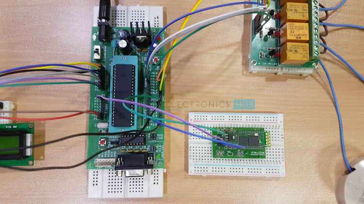
In this project, a Bluetooth module is interfaced to 8051 Microcontroller. This Bluetooth Module receives the commands from the Android application that is installed on the Android device, using wireless communication (Bluetooth Technology). The program which is written to the 8051 microcontroller communicates with Bluetooth module serially to receive the commands. Microcontroller switches the electrical loads automatically based on the commands received from the Bluetooth.
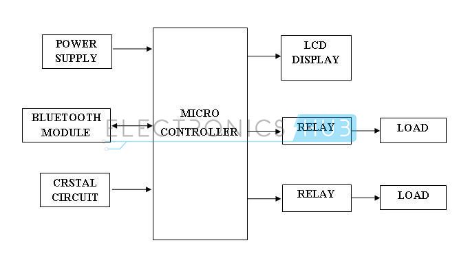
Android Based Home Automation System Circuit Block Diagram
 Bluetooth Controlled Electronic Home Appliances Circuit Diagram
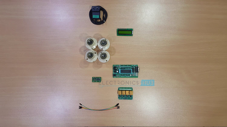
Components Required
Hardware Requirements
- 8051 Microcontroller (AT89C51)
- 8051 Development Board
- 8051 Programmer (Programming Board)
- Programming Cable
- 16 × 2 LCD Display
- 10KΩ Potentiometer
- Bluetooth Module (HC – 05)
- 4 – Channel Relay Module
- Loads (like Light Bulb, Fan, etc.)
- Power Supply
- Connecting wires
- If 8051 Development Board isn’t available, then you might need the following
- 10µF Electrolytic Capacitor
- 2 x 10KΩ Resistors (1/4 Watt)
- 2 x 33pF Ceramic Disc Capacitors
- 0592 MHz Quartz Crystal
- Push Button
- 1KΩ x 8 Resistor Pack
- If Relay Module isn’t available, then you can build the 1 – channel relay circuit (for 1 load) using the following
- 5V or 12V Relay
- BC547 NPN Transistor
- 1N4007 PN Junction Diode
- 1 KΩ Resistor (1/4 Watt)
Software Requirements
- Keil µVision IDE
- Willar Software
- Proteus (for Circuit Diagram and Simulation)
- Android Application installed on Android Device
Android Based Home Automation System Circuit Design
This project consists of a microcontroller, 16 x 2 alphanumeric LCD, 4 – Channel Relay Module, Loads (Light Bulbs are used in the demonstration) and Bluetooth Module.
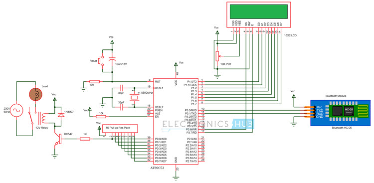
Here, AT89C51 Microcontroller is used. It is an 8 – bit microcontroller and it requires supply voltage of 5V DC. Use 7805 power supply circuit to provide 5V DC to the microcontroller. We can use 9V DC battery or 12V, 1A adapter to provide the supply to the circuit.
For the above circuit additionally you need to connect reset circuit and crystal circuit to the controller to work properly. You can ignore these connections (Power Supply Regulator, Crystal Circuit and Reset Circuit) if you are using an 8051 Development Board.
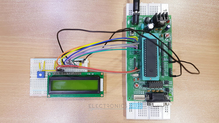
In the above circuit, the LCD display is used to indicate the status of electrical loads and also used to display received data from Bluetooth (Optional Feature).
Here, the LCD Display is interfaced to the PORT1 of the microcontroller in 8 – bit mode i.e. the data pins of the LCD are connected to PORT1. The three control pins of the LCD i.e. RS, RW and EN are connected to P3.6, GND and P3.7 pins respectively.
Also, a 10KΩ POT is connected to the Contrast Adjust pin of the LCD to control the contrast of the display.
The TX and RX Pins of the Bluetooth Module are connected to the RXD and TXD pins (P3.0 and P3.1) of the microcontroller. VCC pin (Pin 40) is connected to the +5V and GND pin (Pin 20) is connected to ground.
The Microcontroller communicates with Bluetooth Module using serial communication (UART protocol). Use a baud rate of 9600 to communicate with Bluetooth.
If you want to change the Bluetooth name and password then you need to use Bluetooth AT commands.
Below are the few Bluetooth AT commands:
- AT — Responds OK. (Used to test the Bluetooth module)
- AT+RESET — Responds OK. (Used to reset the module)
- AT+NAME? — Responds with the module name.
- AT+NAME = <name> — Responds OK. Name should be less than or equal to 20 characters.
- AT+PSWD? — Responds with the existing password.
- AT+PSWD =<password> — Sets module pairing password.
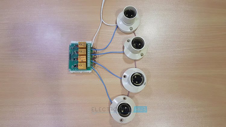
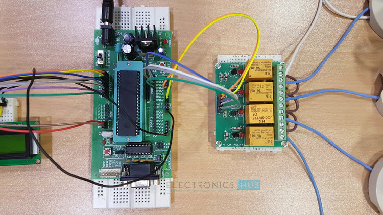
Electrical loads (like Lamp and DC motor) are connected to the P0.0 to P0.3 Pins through the 4 – Channel Relay Module. Here, relays are used to switch AC loads using small DC voltages. NPN transistors are used to drive the relays.
If you are using a relay module, then transistor and other important components to drive the relay are already embedded on the module itself.
NOTE: The Circuit Diagram shows connections of only one load. But the connections to the other loads can also be made in a similar fashion.
Algorithm for Bluetooth Controlled Electronic Home Appliances
- Initialize the LCD and UART protocol.
- Now read the data from Bluetooth module.
- Display the received data on LCD.
- Compare the received string with predefined strings and accordingly switch the electrical loads.
- Display the status of electrical loads on LCD.
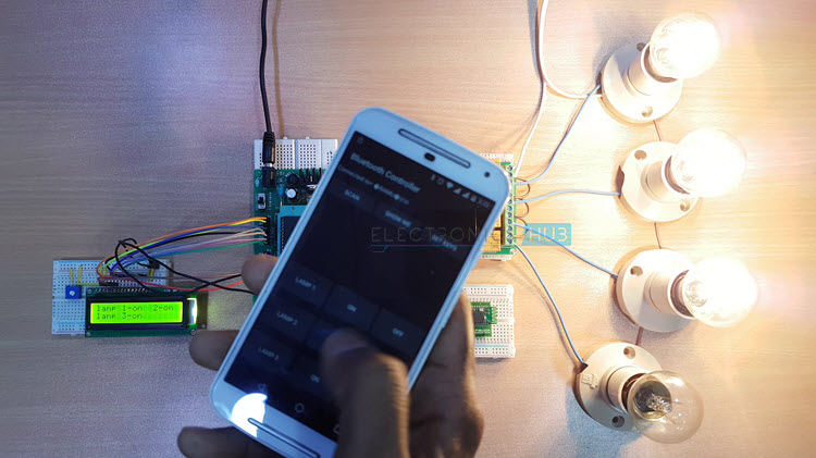
Android based Home Automation System Circuit Simulation Video
Watch the following output video of home automation system using android applications.
DOWNLOAD PROJECT CODE
How Bluetooth Controlled Electronic Home Appliances Circuit Works?
- Write the program to the project in Keil software and create .hex file.
- Burn program to the controller with help of 8051 Programmer and Willar Software.
- Now, give the connections as per the circuit diagram.
- While making the connections, ensure that there is no any common connection between DC and AC supplies.
- Use 5V power supply circuit to provide regulated 5V DC to the microcontroller.
- Switch on the both AC and DC supplies.
- Now relay output pins gets 230V. So, do not touch the load connected pins.
- Install the “Bluetooth Controller” application on your Android Device (Mobile Phone or Tablet)
- Now pair the Android device with Bluetooth module.
- Configure the Bluetooth Controller App as per the 8051 Program.
- Send data to switch ON or OFF the electrical loads.
Related Post: Also read the post – RF remote control for Home Appliances.
Bluetooth Controlled Electronic Home Appliances Project Output Video
Bluetooth Controlled Electronic Home Appliances Project Applications
- This project is used to control the various electrical appliances from the remote area.
- Using this project we can control all the loads using a single remote and a control unit.
Limitations of the Circuit
- In this project the distance between control unit and android device is limited.

79 Responses
dear all
good day
i am very interested in your group and want to join the group
thank you
best regards
Please write a mail to us elktros@gmail.com
Please sir, am highly interested too
In this code….getting error at delay_ms(50)
Pls fix it
the code provided has errors , when compiled in keil it says syntax error at void
can this bluetooth controlled robot be used in any room with only a single remote control , or some connections have to be made in each different room
pls send me the embedded c code
Have u got c code now?
i want to make thesame project to see how it works
please send me the hex file
have you got the hex file of this code
Can we use Arduino instead of 8051
Yes. Search for “How To Make Arduino Based Home Automation” in the website.
Please share source code through email
please send me proteus file and kiel file……thanks
sir… please send me proteus and kiel file…… i will be thankful to this kind act…
thanks for this informative project demonstration i really enjoyed watching it everyday. And i want to do similar project but with more than two appliances, i will like to have the programming code to used as set of reference.
thanks
Good Job…We have already provided the code in the article.Please go through it once
I wan the code because I have similar project.
My project will control the devices only by clicking on buttons, which will be much easier for old people
I did not start on the project, just i am collecting information now.
I am doing the same project, using the same IC, for personal use & also am planning to use a relay driver in place of transistor. Can you help me with the C code?
please post embedded C program..
I need the hex file so that I can use the project for my final year project. I am a student of physics with electronics in Lagos State University. I believe that this project will help slot aged people around me.
hello. i need this project code as i believe it will help me figure out what to get the code for my own project working. the project i am making is different from this one. my project requires communication between devices via bluetooth.
hello. please help me with the code. i believe it will go a long way in helping me with my own project. thank you.
I tried ti generate the hex file by using code that you provided. But, it was showing some errors.So, please help out in this.
How can i download apk file of Bluetooth control??
Please ,How can i get Hex code for this project?
I JUST WANT TO DO SOME THING IN EMBEDDED SYSTEM PLZ PROVIDE ME SO WAY TO DO IT…
Send the the android application code and would love to make the project for college mini project banishing the limitation mentioned above
I want to do this project for my mini project in third year. plz if u can guide me for this project ill be helpful.
iam interested in nowing the code which is written in keil software please can anyone share
Sir your project is too good to operate a device from remote location. I have checked and compiled your code on keil and has also simulated it on proteus but the only thing I am confusing about is the android application, can I get that application too sir. I am making this project to learn about the UART communication with more added devices.
you can use any Bluetooth debugging app from play store
Sir can I use this app available in play store “Bluetooth Viewer LITE”.
can you please send the code required
Please download code from the post itself..
plz send me hex file
How install apk file in android phone
Hello there, I am having a problem with adding Bluetooth libraries to Proteus can anyone please help.
You can use virtual terminal in place of bluetooth to test your program.
Sir, I need the program code to create the android application through which I’ve to control the home appliances. Please send me the coding to aashishsoni11@gmail.com . I also need the microcontroller coding.
Pls suggest any bluetooth app for this
Hey ! i m making a project on remote home security system . being amateur i need a little help . it wil be awesome if you could send me the microcontroller code and algorithm or help me in anyway you can as i m not getting any material on internet 🙂
I have made the above hardware for my project…….the code abcd which I’ve typed on Android phn is not being displayed on the LCD ……kindly help…..give suggestions….
hey! in bluetooth controlled home appliances the given project code is wrong .Because wfen i am compiling in zeil compiler erroe has been generated.
Please let us know what are the errors you are getting…This is a tested code.
Hello!
My friend and I are interested making this project. We are in third year. As amateurs, we would be glad if you provided the project code to us. Also, can you please say which Bluetooth app need to be downloaded?
suggest me the suitable app for this project…
sir i interested but i have one problem , i have 89c51 ic , i already install program , but i want to know it is compulsory to connect crystal in circuit, i confuse bcs in your circuit diagram not show crystal and also one question which android app download for this project please sir reply me fast,
Interfacing with lcd not working,when we try to simulate the programme in proteus lcd and loads are not connected .. please help us
PLEASE GIVE ME THE ‘APK’ FILE
thank you
can anyone help me to remove this error “ERROR C141 IN LINE 1 OF C:\Keil\C51\BIN\..\INC\uart.h: syntax error near ‘void’ ”
“
sir i need hex file of the code.or combined code
I need the hex file
hello sir
i got an error while compiling bluetooth controlled home appliances the given project code.
the error is
uart.h(1): error C141: syntax error near ‘void’
please help me for correct code
thank u
please provide the proteus file. An error is occuring while simulation
please send me the proteus file.. an error is occuring while simulting the proteus
I’m interested to join with your group
WHAT IS THE NAME OF THE BLUETOOTH APP U USED IN YOUR ANDROID PHONE FOR THIS PROJECT?
dear sir please tell me. The C compiler name of microcontroller AT89C52
Want a hex code for this project
Help pls
For bluetooth cintrolles
Which apk file is used for bluetooth controlled electronic home appliances
I like your video which you have uploaded . I made this project at home. I want programming for PIC16f877a for this project where we can home automation by bluetooth of android.
Hi, i have similar circuit just like yours but the output I place with a kettle. How the schematic circuit would become if the output I use is kettle. I hope you will guide me to build this circuit and i would really appreciate it ;-).
Sir where is keil code of this project
Hello sir i can’t burn program in AT89c51 microcontroller through flash magic.How to burn a program for same or Can i used another microcontroller place it?
I have used the code and given apk file still led of relay is not glowing. HELP out pls!
hai sir i am doing project on home automation, so i need information on TFT lcd, relay
what is the name of that android app
Hi, The App is called “Bluetooth Controller”. Search it in Google Play Store.
Can we implement this project using arduino? If yes, then can you share the code?
Regards.
There is already a project using Arduino. The title is “How To Make Arduino Based Home Automation Project via Bluetooth?”
There is no app in playstore
We are working on our own app. It will be available soon.
superb
How to increase the distance between the circuit and android
is this for beginners.
this project is transaction paper based project or mini project.
this is situable for final year project or not?