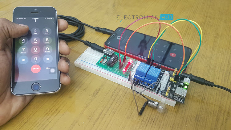
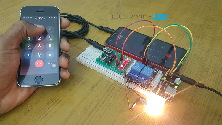
In this project, I will show you how to design a simple circuit called Mobile Controlled Home Appliances without Microcontroller. That’s right. Using this circuit, you can control your home appliances without any microcontroller and programming.
Introduction
Sometimes, unfortunately, we may forget to switch off the appliances like fans and lights while going outside and as a result we end up paying the price for it. To solve these types of problems, this article explains you how to design a simple circuit, which will on the devices remotely and devices will off automatically after the specified time interval.
Till now we have seen so many home automation projects that control the devices or appliances from the remote place but the main advantage of this circuit is simple because we are not using any microcontroller in this circuit and it uses the components which are easily available in the market. We have already seen How DTMF Controlled Home Automation System Circuit Works using Microcontroller in the earlier post.
Mobile Controlled Home Appliances Circuit Principle
The main principle used in this circuit is DTMF communication. DTMF is an acronym for Dual-Tone Multi-Frequency. When you make a call to customer care service they will ask you to press the numbers to provide the appropriate services. If you think about how they are recognizing the pressed number then DTMF comes into picture.
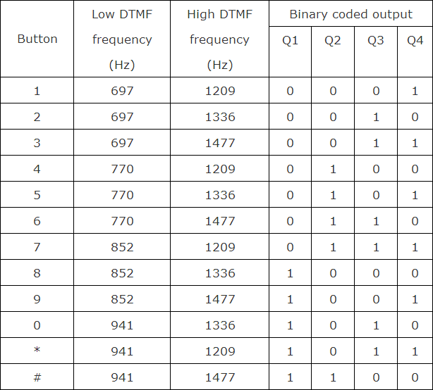
If you press the button in your mobile phone, a tone is generated with 2 frequencies. These 2 frequencies of the tone are row and column frequencies of that particular button. For example if you press the button 1 then a tone generated with the sum of 697 Hz and 1209 Hz. The below table show you the row and column frequencies of a DTMF keypad.
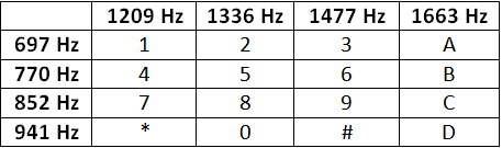
These generated tones are decoded at switching centre to determine which button is pressed. Now we have to use this DTMF tones to control the devices from remote area. To decode these DTMF tones at receiver we need to use a DTMF decoder. Decoder IC converts these tones into the digital form. For example if you press number ‘5’ in mobile keypad then the output of DTMF decoder is ‘0101’.
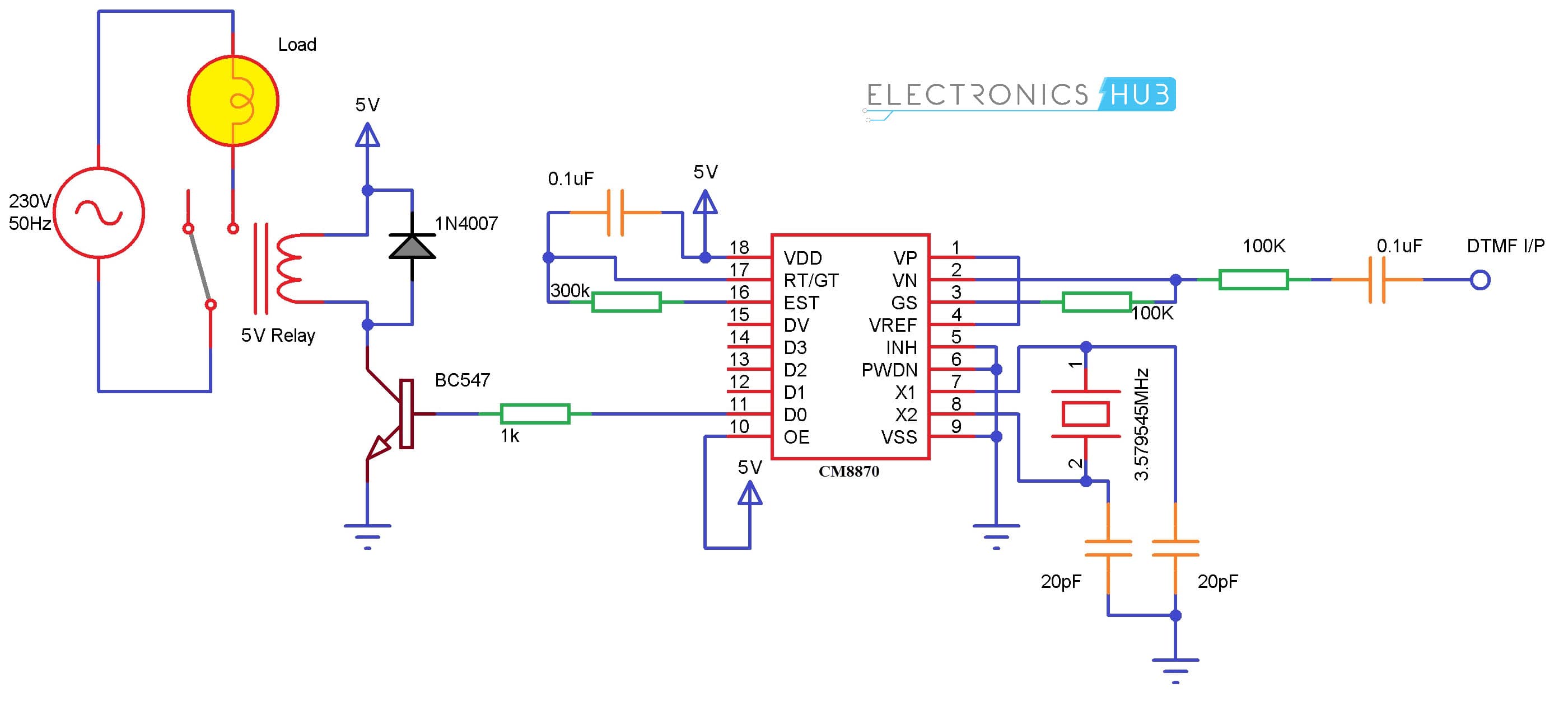
Cellphone Controlled Home Appliances Circuit Diagram without Microcontroller
Circuit Components
- MT8870 DTMF decoder
- 5V relay Module
- 230V, 50 Hz AC motor (optional)
- BC547 Transistor
- 3.579545 MHz crystal
- 3.5mm audio jack
- LED
- 1N4007 Diode
- 0.1uF Ceramic capacitors – 2
- 20pF Ceramic Capacitors – 2
- Resistors (1/4 watt) – 1KΩ, 100KΩ x 2, 300KΩ
- Connecting wires
- Bread board
Mobile Phone Controlled Home Automation System Design without Microcontroller
It would be best if you choose dedicated modules for the DTMF Decoder and relay as building them from scratch might be tedious. If you are going with modules, then all you need to do is to make a few small connections using jumper cables as all the components are readily placed.
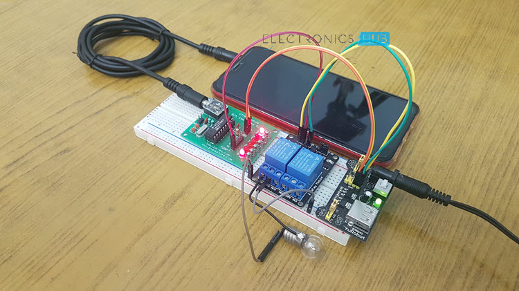
Connect an audio cable in the 3.5mm audio jack between the receiver mobile phone and the DTMF Receiver board. The D0 pin (usualy marked as Q1) is connected to the input of the relay module.
Working
The main components in this circuit are MT8870 DTMF decoder (a variant called CM8870 IC is used here). When you make a call to the mobile which is connected at the receiver end, the MT8870 IC provides high pulse at 15th pin after receiving a valid signal. Now if you press 1 from the mobile the output of the decoder IC at pins Q1, Q2, Q3 and Q4 will be 1, 0, 0 and 0 respectively.
As the Q1 pin is connected to the input of the relay, it will be activated and as a result, the load will be turned ON. To turn off the load, press any number that makes Q1 as 0 i.e. 2 for example.
The following tables shows the Binary outputs corresponding to the buttons pressed on the mobile phone.
[Also Read: How To Make an Adjustable Timer ]
How to Operate DTMF Controlled Home Automation System without Microcontroller?
- Give the connections as per the circuit diagram.
- While giving the connections, make sure that there is no common connection between AC and DC supplies.
- Insert the audio jack to the receiver mobile and keep the receiver mobile in auto answer mode.
- Receiver mobile should be in general profile and keypad tones should be in sound mode.
- Now make a call to the receiver mobile as it is in the auto answer mode it will pick up the call automatically.
- When the call is attended, press number 1 in your mobile. This will activate the relay.
- To turn off the relay, press 2.
DTMF Mobile Controlled Home Appliances Circuit Applications
- Used to control the home appliances
- We can control the robot using this technology
- This circuit is used to control the water tank motor by setting the on time
Circuit Advantages
- We can avoid the wastage of power
- We can control the devices from long distances also
Circuit Limitations
- Security is not provided, anyone can control by making a call to the receiver mobile
- Number of devices which we can connect to the circuit is limited.

42 Responses
Nice project, you people are providing awesome information for students.
have you tried this project. not getting a pot of 4.7 mega ohm what you instead of it?
is anyone do this project ? if ,plz send me limitation , precaustion about this project.
Do u have vedio for this project
is circuit works properly?
dude improve ua grammar bro….
Yours too!
thanks
welcome
What is the acuurate value of c4 & rv1 if we want to oprate the circuit for 45min ples ans it
It’s very useful project
so powerful project.
good project and easy project
Did u try this project , I didn’t get output , before make call the led and motor will on and mobile does not communicate to board wat to do
have you done this project?
can you give clear pic of decoder connection?
nice project for garib log
Thanks for the sharing…i like
Thanks for the sharing, it’s look good
Great project, would love to build one. Plse how much in cost would it cost? Any estimate would do
what is that. X1 that is been mentioned in your circuit …..what we must give there input …plz tell me sir
It is 3.57 MHz crystal…
nice one.but can we use smart phone as receiver of 3.5mm jack and how we will identify which appliances is turned on which is not.can u plz send the video of the same
where would i connect the load on the circuit
In place of motor any ac load is connected
project did not run .plz tell me what i do!!!
can we use relay driver or motor driver ic instead of 555 timer ic
What is the reason after the digit 7 to be the signal coming from the DTMF is the right unless the cuircuit would not work????
Thanks
What the reason after choosing digit 7 to be the trigger of the cuircuit not other digits?????/
Thanks
This is a very good project.well done keep it up.
wow nice
can any MT8870 operate as the one in the circuit answer? thank you
Why need 4 LED in pin 11,12,13,15
sir,
I need full circuit diagram, what are component is used full details .plz replay soon as possible. I want urgent
capacitor for c4: 470uF 50v is better choice..
when the ring stops. that time device will remain on or off.. If the device off then how i device remain on and cut the call .after when i want to off this device i call back and then device off.
any video tutorial available for this project?
in my city,pot- 4.7M ohm is not availablle.can anyone suggest me what to do? and what is the function of decoder 14th pin?
thanks in advance.
bhai ji agar ye ckt aapke paas ho to price bata do plz
Sir may I know mt 8870 dtmf decoder ic is a receiver
Yes. MT8870 is a DTMF Receiver.
4.7 M pot is not available
So..
Can we use 4.7 M resistor instead of it
What was the price of the whole circuit and is workable please clear my doubts
hello friends
is this implementing in modern days
i want that information guys