The concept of Home Automation is gaining popularity as it helps in reducing human effort and errors and thus incBT Voice Control for Arduinoasing the efficiency. With the help of Home Automation system, we can control different appliances like lights, fans, TV, AC etc. Additionally, a home automation system can also provide other features like security, alarms, emergency systems etc. can be integrated.
There are many types of Home Automation Systems like Bluetooth Controlled, Internet Controlled, RF Controlled, Remote Controlled (IR Remote) etc. Each type has its own advantages and disadvantages. In this project, we have designed a Voice Activated Home Automation system, where different appliances are controlled by sending a Voice Command.
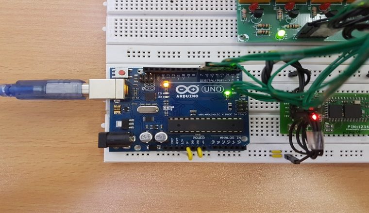
The Voice Activated Home Automation project is implemented using Arduino UNO, Bluetooth and a smart phone. Further sections will explain circuit diagram, components required and working of the project.
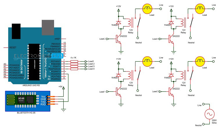
Voice Activated Home Automation Circuit Diagram
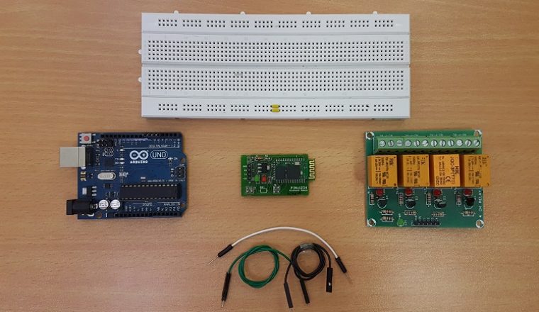
 Components Required
- Arduino UNO – 1
- HC – 05 Bluetooth Module – 1
- Smart Phone or Tablet – 1
- 2N2222 NPN Transistor – 4
- 12V Relay – 4
- 1 KΩ Resistor – 4
- 1N4007 PN Junction Diode – 4
- Power Supply
- Connecting Wires
- Breadboard (Prototyping Board)
- App for transmitting voice to Bluetooth
Components Description
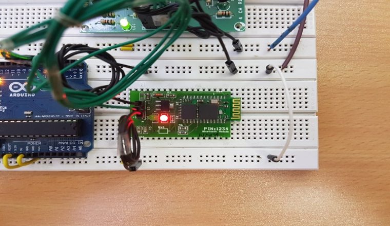
Bluetooth HC – 05: For wireless communication, we used Bluetooth Technology and the module used for this is HC – 05. This module can be interfaced using UART protocol with a wide range of programmable baud rates but the default baud rate is 9600 bps. HC – 05 Bluetooth Module can be configured as either master or slave, whereas another module HC – 06 can work only in slave mode.
The following image shows the HC – 05 Bluetooth Module used in this project. In this module, there are pins for VCC (5V), GND, TX and RX.

BT Voice Control for Arduino: This app is developed by SimpleLabsIN for voice based Arduino projects. This Android App will use the phone’s voice recognition feature and will convert the voice commands to text and transfer the string via Bluetooth.
The app can be downloaded from here BT Voice Control for Arduino
If you are familiar with any other similar app, you can always use that.
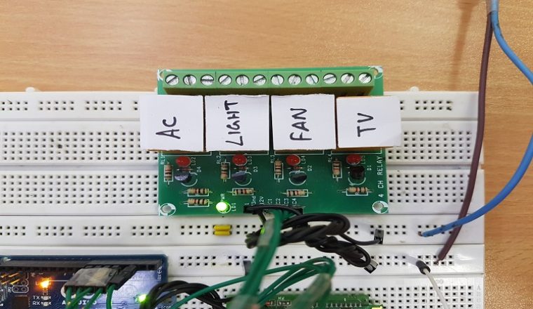
Relay Board (4 – Channel): A Relay is used to connect a small current transistor circuit with a large current AC circuit. In this project, we have used a pre-built relay board with 4 – channels.
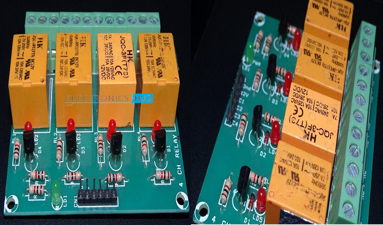
NOTE: Be cautious when using Relay board with AC Mains Supply.
Circuit Design
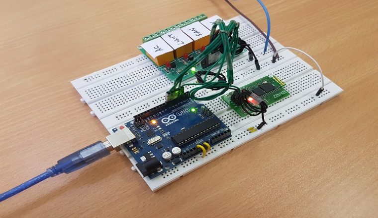
We will now see the design of the Voice Activated Home Automation circuit. First, we will connect the Bluetooth Module to the Arduino. Since Bluetooth uses UART protocol, we need to use the RX and TX pins of the Arduino. We will be using “SoftwareSerial” library to define our own RX and TX pins (Pin 2 is RX and Pin 3 is TX).
NOTE: We have left out the Bluetooth’s RX and Arduino’s TX connection as it is not used. In case you face a problem, connect a voltage divider to convert the Arduino TX’s 5V signal to Bluetooth RX’s 3.3V.
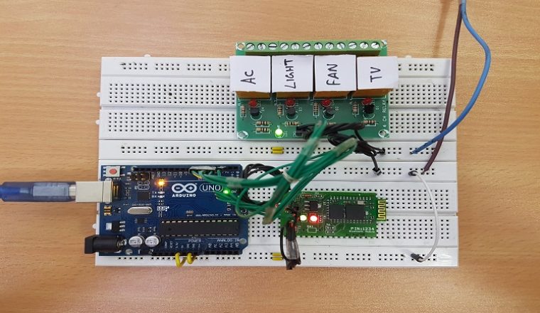
Next, we will connect the relays to the Arduino. Since we used a readymade relay board with 4 – channels, all we need to do is to connect the inputs of the individual relays to the Arduino. For detailed connection like the resistor, transistor, diode and relay, refer the circuit diagram.
NOTE: We did not connect any load to the relay but you can always connect some small loads and check out the functioning. Be extra careful while using AC Mains with relay board.
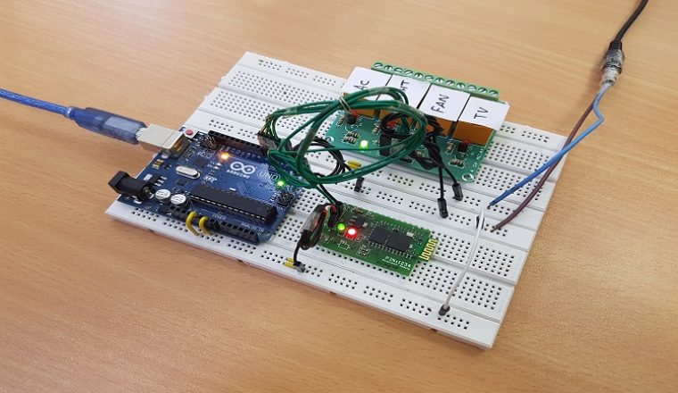
All the necessary connections are explained in the circuit diagram.
Working of the Project
In this project, a simple Voice Activated Home Automation system is designed. Voice commands are used to control different appliances. We will now see the working of the project. All the connections are made as per the circuit diagram above.
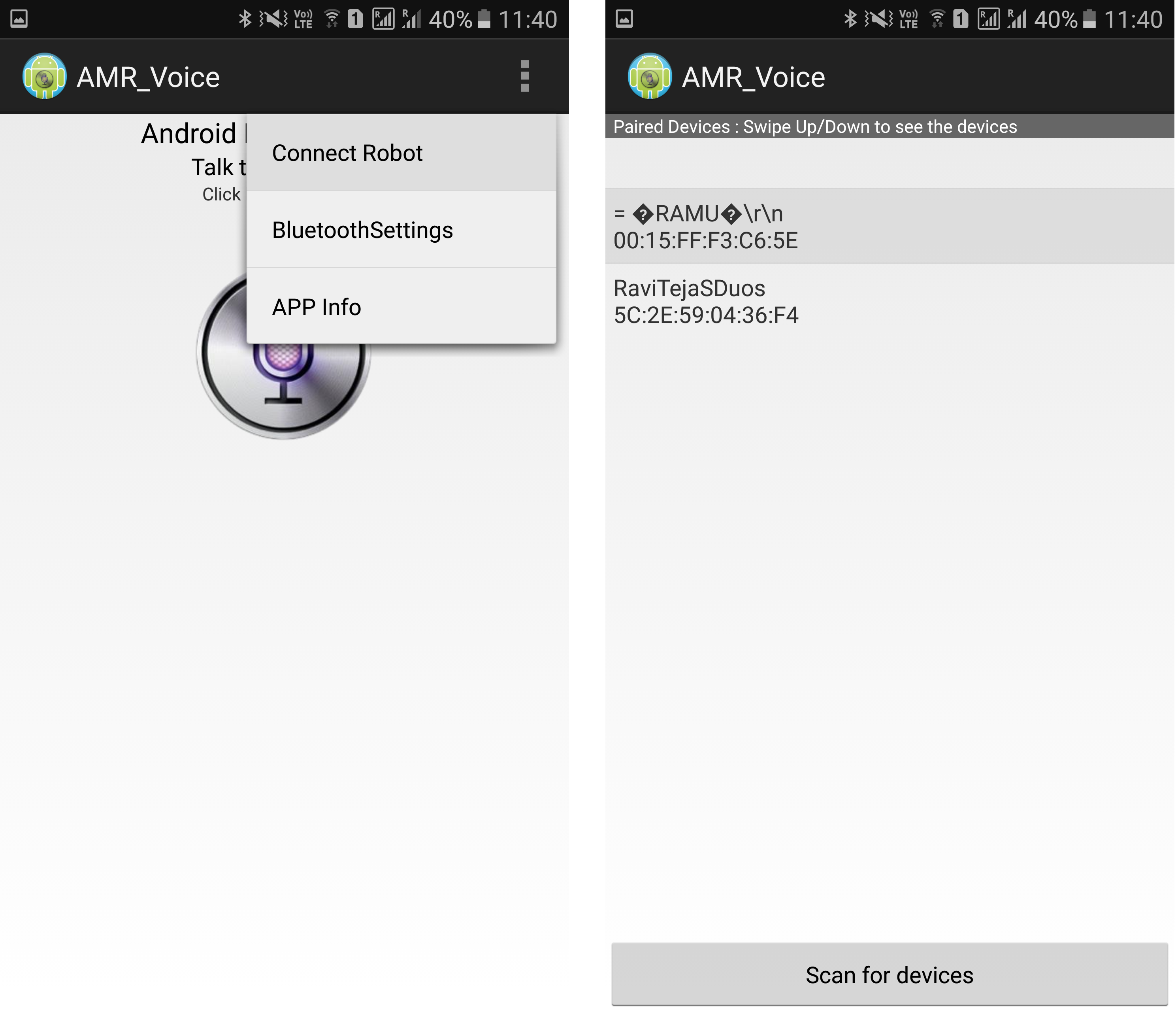
After making the necessary connections, we have to switch on the power supply to the circuit. Now, we need to pair the Phone’s Bluetooth to the HC – 05 Bluetooth Module. Before that, we have to install the App mentioned above in the phone. The home screen of the app looks something like this.

Next step is to connect the phone with the Bluetooth module. For this, choose the option “Connect Robot” and select the appropriate Bluetooth Device. If the devices aren’t paired earlier, we need to pair them now using the Pin of the HC – 05 Bluetooth Module.
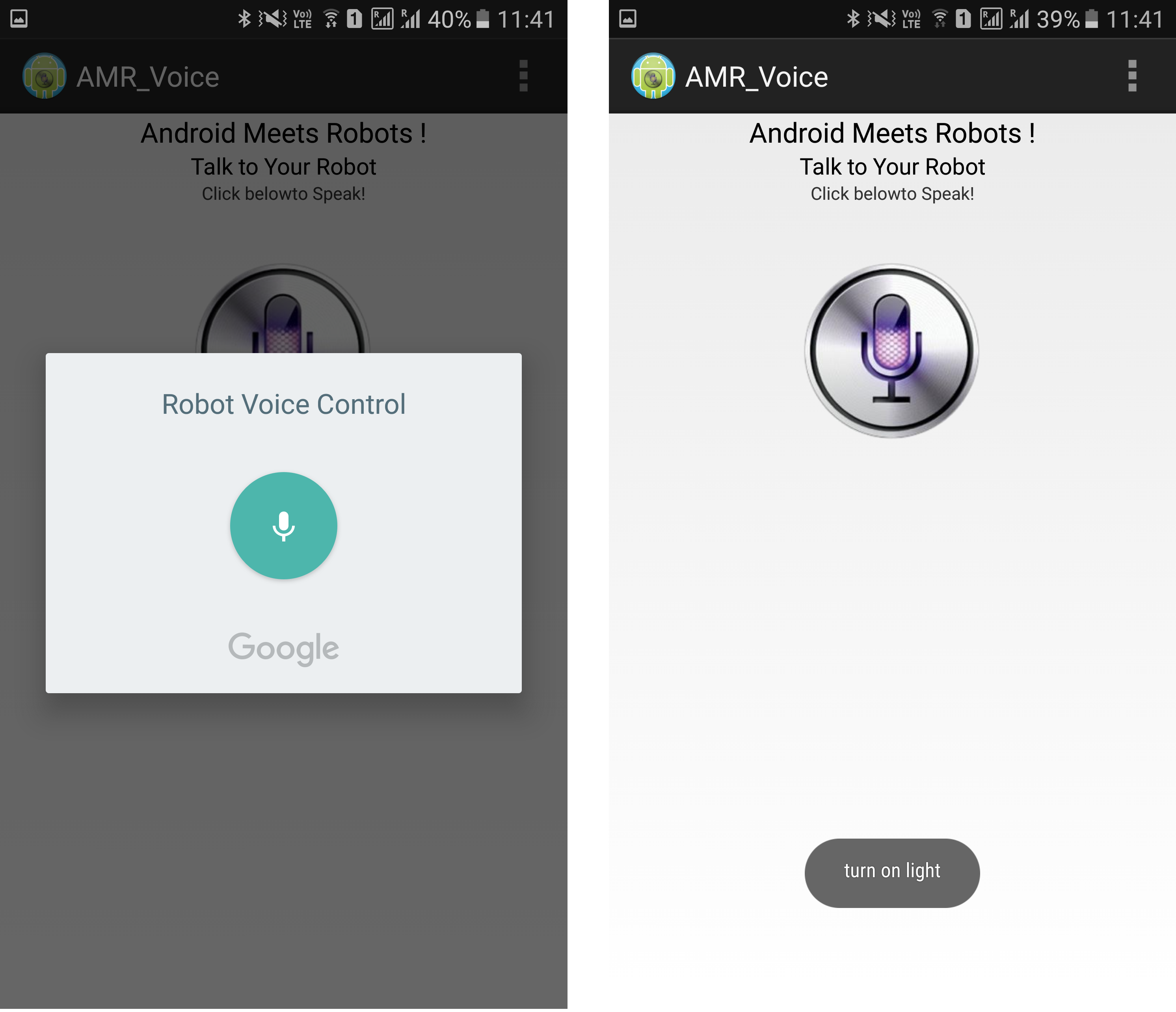
After successful connection, the devices are ready to transmit data. For that, press the press microphone icon on the app and start giving voice commands.
NOTE: Make sure that the voice recognition feature is enabled on the phone (this is usually associated with Google app).
For example, if we press the microphone icon and say “turn on light”, the app will recognise the command and the transfers it to the Bluetooth Module. Also, the command gets displayed on the screen for our reference.
When the string “turn on light” is detected by the app, it will send the string as “*turn on light#”. So, the actual message received by the Bluetooth Module is in the format of “*Message#”. The reason for padding the ‘*’ and ‘#’ at the begging and end of the string is to identify the starting and ending of the message.
We are able to delete the ‘#’ from the string but left out the ‘*’ in order to identify the starting of the string. The received message is compared with some predefined strings and if the message matches with any of them, then corresponding action like turning on or turning off the load happens.
We have used the following commands: “turn on AC”, “turn off AC”, “turn on light”, “turn off light”, “turn on TV”, “turn off TV”, “turn on fan”, “turn off fan”, “turn on all” and “turn off all”.
Code
Applications
- The Voice Activated Home Automation system will help us control different loads (electrical appliances) with simple voice commands.
- This kind of system is very useful for people with disabilities.
- Further, the project can be expanded by adding different sensors (light, smoke, etc.).
Construction and Output Video

38 Responses
thanks alot for this
where is the programming file for arduino???
Mention disadvantages that will help students to further development
all cannot mention ok mind your words.
Hello,
I want to ask how we can pair the Bluetooth Module.
Hi, Check this video. https://www.youtube.com/watch?v=dHwInrh5niU If you are pairing the Bluetooth Module for the first time, you probably have to enter the PIN of the Bluetooth Module on the phone. It is usually printed on the Module (1234 or 0000).
Please send a exact circuit connection so it will be easier to be identify.
Hello..
I want to know that if this project really switch on or off the light tv or fan in home or its just a demonstration..
Hi,
If you connect the loads to the relay, then yes, the loads will be switched on and off.
How to buy this circuit?
Yes it does
Hello I did this project with just an led in pin 11 and I used an HC-06 instead of a 5 module. I modified your code and was able to get the app along with my UNO to work. The only problem is I cant get my LED to blink. is there anyway you can tell me what whats wrong in my code?
#include
const int rxPin = 0;
const int txPin = 1;
SoftwareSerial mySerial(rxPin, txPin);
int light = 11;
String data;
void setup()
{
Serial.begin(9600);
mySerial.begin(9600);
pinMode(light, OUTPUT);
digitalWrite(light, LOW);
}
void loop()
{
int i=0;
char ch=0;
data=””;
while(1)
{
while(mySerial.available()<=0);
ch = mySerial.read();
if(ch=='#')
break;
data+=ch;
}
Serial.println(data);
if(data=="*turn on light")
{
digitalWrite(light,HIGH);
Serial.println("light on");
}
else if(data=="*turn off light")
{
digitalWrite(light,LOW);
Serial.println("light off");
}
}
is it a smart idea to connect arduino with 12v?
Vin , check that pin
Can you give me a exact circuit connection
please say how to compile the code
IN which software code is compiled
Arduino IDE.
Is that ARDUINO 1.8.5
The latest version of Arduino IDE would be better.
what is the latest soft ware for ardunio
please say which type of ardunio uno is used…
please give app link
Sir
Can we used 24v relay with it
Exact circuit diagram will help us please mention the source of it..!
why AC and TV do not work?
Only the light and Fan work.
i use optocoupler relay high/low level trigger.
is that because of relay?
#include
const int rxPin = 2;
const int txPin = 3;
SoftwareSerial mySerial(rxPin, txPin);
String voice;
int
led1 = 5, //Connect LED 1 To Pin #5
led2 = 6, //Connect LED 2 To Pin #6
led3 = 7; //Connect LED 3 To Pin #7
//————————–Call A Function——————————-//
void allon(){
digitalWrite(led1, HIGH);
digitalWrite(led2, HIGH);
digitalWrite(led3, HIGH);
}
void alloff(){
digitalWrite(led1, LOW);
digitalWrite(led2, LOW);
digitalWrite(led3, LOW);
}
//———————————————————————–//
void setup() {
Serial.begin(9600);
pinMode(led1, OUTPUT);
pinMode(led2, OUTPUT);
pinMode(led3, OUTPUT);
}
//———————————————————————–//
void loop() {
while (Serial.available()){ //Check if there is an available byte to read
delay(10); //Delay added to make thing stable
char c = Serial.read(); //Conduct a serial read
if (c == ‘#’) {break;} //Exit the loop when the # is detected after the word
voice += c; //Shorthand for voice = voice + c
}
if (voice.length() > 0) {
Serial.println(voice);
//———————————————————————–//
//———-Control Multiple Pins/ LEDs———-//
if(voice == “*switch on”) {allon(); Serial.println(voice); } //Turn Off All Pins (Call Function)
else if(voice == “*switch off”){alloff(); Serial.println(voice); } //Turn On All Pins (Call Function)
//———-Turn On One-By-One———-//
else if(voice == “*TV on”) {digitalWrite(led1, HIGH);}
else if(voice == “*fan on”) {digitalWrite(led2, HIGH);}
else if(voice == “*computer on”) {digitalWrite(led3, HIGH);}
//———-Turn Off One-By-One———-//
else if(voice == “*TV off”) {digitalWrite(led1, LOW);}
else if(voice == “*fan off”) {digitalWrite(led2, LOW);}
else if(voice == “*computer off”) {digitalWrite(led3, LOW);}
//———————————————————————–//
voice=””;}} //Reset the variable after initiating
THIS IS THE CODE I’m using. I’ve used led’s in place of relay, so modified the code
please cross check and tell me where I’m doing wrong.
Please tell me the reason that why when I give it any command like “turn on light” it is recognized by app and it displays turn on light in bottom of screen but nothing happen no light is turned on it seems like relay is not receiving command.
Please tell the troubleshoot .
Same problem .Please anyone help to rectify the problem .
Need help in purchasing Voice Activated Home Automation and installing for my house.. wht is the cost
This is just a prototype. Just to understand the concept of the project.
sir , please tell wht Rx pin of bluetooth is not connected with Tx pin of Ardino . How it is receiving commands ?
this App is not connecting with Bluetooth HC-05
Thanks for your help and it is very useful for me.I thank again
Can I connect small versions of fans and lights to make it actually look like a house. Will it still work?
If i can, how do i do so?. I basically want small bulbs and exhaust fans connected to the above circuit fitted into a house that will make it look really cool.
Hey there I am getting an error while uploading its showing invalid library found
Hi bro . Can you drowing the circuit for this project??
is this code real or just a piece of junk. I did not do the circuit but is this going to work. can you pls how to download this code.
What is serial software how can i instal that