DTMF based Load Control System using 8051 Microcontroller is a simple project that helps is controlling different loads (electrical appliances) with the help of DTMF Technology. DTMF or Dual Tone Multi Frequency is a signaling technique that is often used in the field of telecommunication (telephones to be specific).
In the DTMF based Load Control System using 8051 project, we are using different communication technologies like DTMF and GSM for controlling our home appliances using a cell phone (mobile phone).
CAUTION: Be extremely careful as you will be dealing with 230V AC Mains supply.
Output Video
Principle of DTMF based Load Control System using 8051
The principle of operation of the DTMF based Load Control System using 8051 Microcontroller is based on the DTMF Technology.
DTMF Technology is used in telephones (mobile phones or fixed lines), where when a key or button is pressed on the phone, a corresponding and unique tone will be generated. This tone is a combination of two different frequencies.
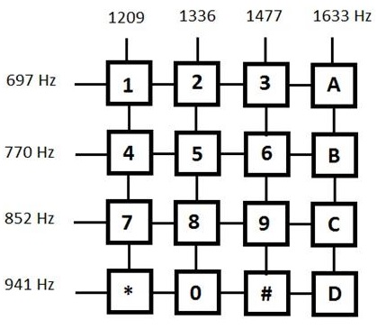
Every key is associated with two frequencies and up on pressing the key a tone, which is an overlap of those two signals, is generated. In a typical telephone keypad, there are 12 keys i.e. 0 to 9 numeric keys and two symbol keys (Hash # and Asterisk *).
These 12 keys are placed in 4 rows and 3 columns. Additionally, a fourth column consisting of letters A, B, C and D is also included in DTMF Technology.
The following image shows the layout of a typical telephone keypad and the corresponding tone frequencies.
In this project, we will be decoding the tones pressed on the phone and accordingly turn ON or OFF the load. For this, we will be using a dedicated DTMF Decoder IC – HT9170B.
Related Article: DTMF Controlled Robot without Microcontroller
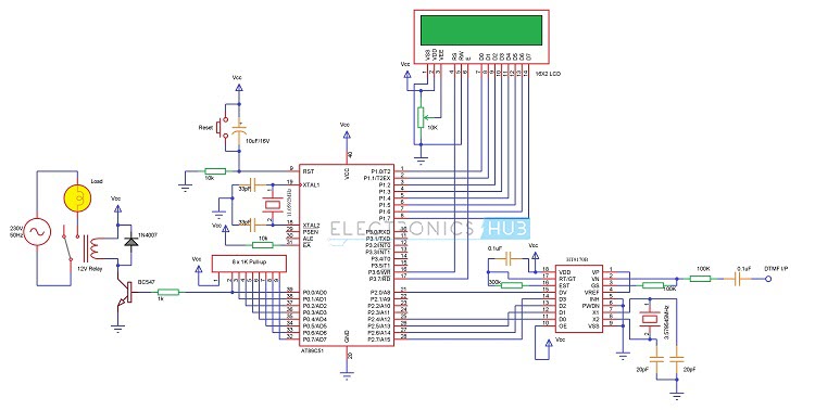
Circuit Diagram of DTMF based Load Control System using 8051
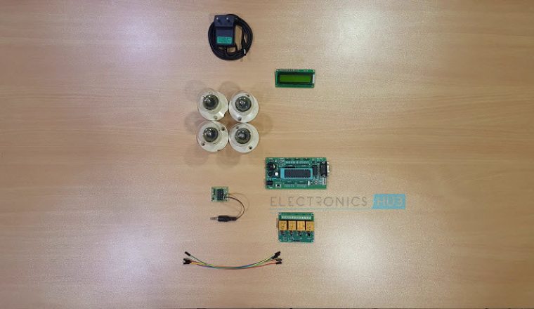
Components Required
- 8051 based Microcontroller (AT89C51)
- 8051 Programmer Board
- 11.0592 MHz Quartz Crystal
- Push Button
- 2 x 33pF Capacitor
- 2 x 10 KΩ Resistors (1/4 Watt)
- 10µF Capacitor
- 1 KΩ x 8 Pull – up Resistor Pack
- 16 x 2 LCD Display
- 10 KΩ POT
- HT9170B DTMF Decoder IC
- 3.579545 MHz Crystal
- 2 x 20pF Capacitor
- 2 x 100 KΩ Resistors (1/4 Watt)
- 0.1µF Capacitor (100nF)
- 300 KΩ Resistor (1/4 Watt)
- 5V or 12V Relay
- BC547 NPN Transistor
- 1N4007 PN Junction Diode
- 1 KΩ Resistor (1/4 Watt)
- Keil µVision IDE
- Willar Software
- Two mobile phones (one at the circuit and one for calling)
Also read this interesting post: DTMF based Home Automation
How to Design DTMF based Load Control System using 8051?
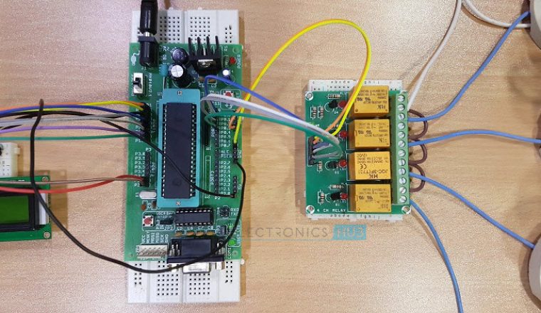
First, you have to connect the basic components for oscillator circuit and reset circuit to the microcontroller. If you are using a development board, then these connections will be already established.
Next, you have to connect the LCD Display. LCD is used in 8 – bit mode. So, connect all the 8 data pins of LCD to PORT1 of the 8051 Microcontroller. Connect the three controls pins of LCD as follows: RS to P3.6, RW to GND and E to P3.7.
To control the contrast of the LCD Display, connect a 10 KΩ POT to its Pin 3.
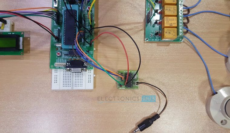
There are a lot of connections associated with the DTMF Decoder IC. Hence, we have used a dedicated DTMF Decoder Module with all the connections already made. The circuit diagram clearly mentions the necessary connections with respect to the DTMF Decoder IC.
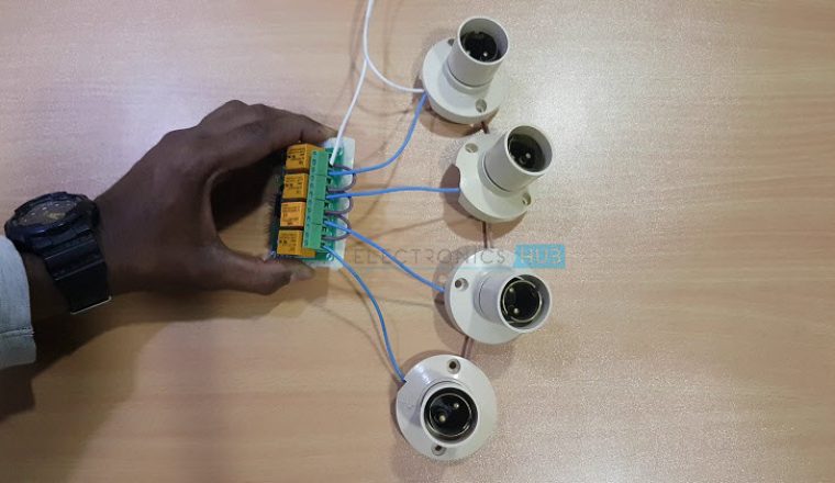
Finally, you have to connect the load to the microcontroller. A relay is connected to PORT0 pin P0.0 of the microcontroller through a transistor.
The circuit diagram and components mentioned above are specifically for controlling one load. For multiple loads, you will need a similar set of components.
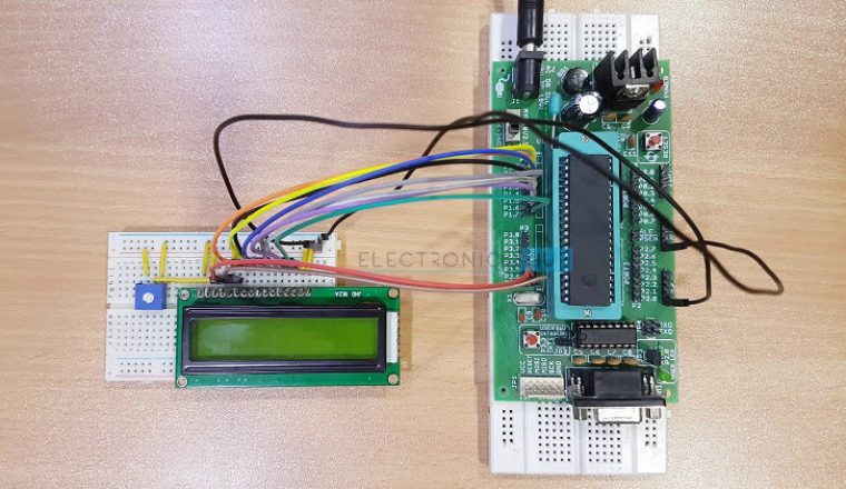
How to Operate the DTMF based Load Control Circuit?
- First, connect headphone to the 3.5MM Jack on the phone. The wires of the headphones are connected to the DTMF I/P of the circuit.
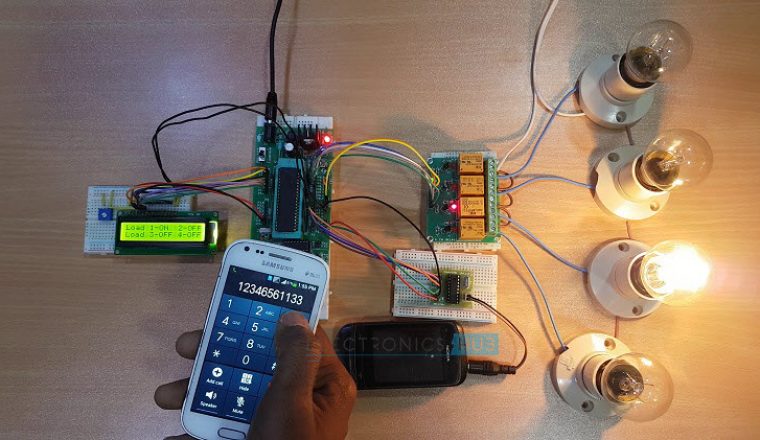
- Power ON the circuit and all the loads are OFF by default.
- For testing the circuit, open the dialer in the phone connected to the circuit and press digit 1.
- As per the program, when tone for 1 is decoded by the DTMF Decoder IC, microcontroller will turn ON the Load 1.
- When you press the key 1 once again, the microcontroller will turn OFF the Load 1.
- Now, in the phone connected to the circuit, set the option to automatically answer a call, when headphone is connected.
- Using the second phone, dial the number corresponding to the first phone (the one connected to the circuit).
- The call will be automatically answered.
- When you press 1 on the phone in your hand, the tone will be transferred and will be detected by the DTMF Decoder.
- Hence, the microcontroller will turn ON load 1.
- Similarly, you can control other loads as well.
Algorithm for Program
- If you refer to the datasheet of HT9170B, it specifies the output data corresponding to the key presses.
- For example, for key 1, the data on the output pins of the DTMF Decoder IC will be as follows: D3-D2-D1-D0 = 0-0-0-1.
- You can use this data in the program of the 8051 microcontroller to detect key 1.
- Similarly, there are unique data outputs for all the keys.
- In order to detect a valid tone, you can use the DV pin of the DTMF Decoder IC (Pin 15). This pin will become HIGH when there is a valid tone at the input. Otherwise, this pin remains LOW.
DOWNLOAD PROJECT CODE
Advantages of DTMF based Load Control System
- You can use the DTMF based Load Control System using 8051 Microcontroller to remotely control any loads using GSM and DTMF technologies.
- We can turn ON or OFF the appliances from anywhere and at any time.
- We need not worry if forgot to switch OFF any appliance while we are going out as we can turn them OFF at our convenience.
Limitations of DTMF based Load Control
- Anyone with the mobile number of the phone at the circuit can control the loads.
- You can control only 16 loads at the maximum.

4 Responses
Usually I do not learn post on blogs, but I would like to say that this write-up very pressured me
to check out and do it! Your writing taste has been amazed me.
Thank you, very nice article.
Hello ravi, Amazing project!! Hats off to you.
I wanted to do this as my major project and I`m not able to download the code. Could you please send me the code? Please, it is very important to me.
This project is simple yet amazing. Could you please send me the project code it would really help me a lot.
Can you please upload the code for this project