RFID Security Access Control System using 8051 Microcontroller is an RFID Technology based security system. Using this system, authorization of personnel is carried out with an RFID card and only those with access can enter a secured area.
The security of any organisation is a priority for the authorities. The security concern is for the physical property and also for the intellectual property.
For this reason automatic identification and access control system has become necessary to overcome the security threats faced by many organisations.
Outline
Toggle- RFID Security Access Control System using 8051 Microcontroller
- Construction and Output Video
- RFID Security Access Control System using 8051 Microcontroller Principle
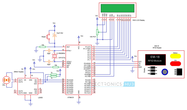
- RFID Security Access Control System using 8051 Microcontroller Circuit Diagram
- Components
- RFID Description
- Circuit Design
- How RFID Security Access Control System Works?
- DOWNLOAD PROJECT CODE
- Advantages and Applications
- Limitations
RFID Security Access Control System using 8051 Microcontroller
This project deals with an interesting manner of security access control with the help of RFID Technology, where only people with valid cards are allowed to access the door or any secure area.
Construction and Output Video
RFID Security Access Control System using 8051 Microcontroller Principle
The principle of operation of this project is based on the working of the RFID Circuit.
A Passive type RFID Card is used in this project. When this card is placed near the RFID Reader Module, the antenna coil in the Reader energies the coil in the RFID card through mutual induction. As a result, the microchip in the reader also gets enough power to turn it on.
Now the coil in the reader acts as an antenna and transfers the data in the microchip to the reader module through radio communication.
The reader module, then communicates with the microcontroller through UART protocol to transfer the data received from the card.
RFID Security Access Control System using 8051 Microcontroller Circuit Diagram

Components
RFID Description
Radio Frequency Identification or simply RFID is a wireless technology generally used for automatic identification and data collection.
RFID technology is used for accessing data from a uniquely identify RFID card or tag by combining the radio frequency and microchip technologies i.e. the data is retrieved or stored into the RFID cards without making any physical contact.
With the help of RFID technology we can create smart systems that can be used personnel identification, product monitoring, individual or organisation security, transportation, maintenance of inventory and supply chain tracking.
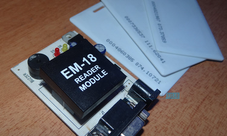
RFID systems usually comprises of three components: an RFID Card, an RFID Reader Module and a host device.
RFID Card or Tag consists of the data in the embedded microchip. RFID Reader is used to read the data from the RFID Card and transfer it to the host device.
The communication between the Reader and Card is using Radio Technology whereas the communication between RFID Reader and the host device like a microcontroller is through serial protocol.
RFID tags are generally classified into two types: Active RFID Tags and Passive RFID Tags.
Active RFID Tags are battery powered and they have an electronically erasable and programmable memory. So, the necessary data can be written in to the memory by the user and read using a RFID Reader.
As they are battery powered devices, Active RFID Tags can communicate with the RFID Reader over distances larger than 100 feet.
Passive RFID Tags on the other hand, do not contain any battery. Passive RFID Tags consists of a coil and a microchip. The coil acts as an antenna as well as the source of power through induction.
The microchip is a read only type memory and the user can only read the data that already stored by the manufacturer. Passive RFID Tags are used for short distance communication, usually 10 feet or less.
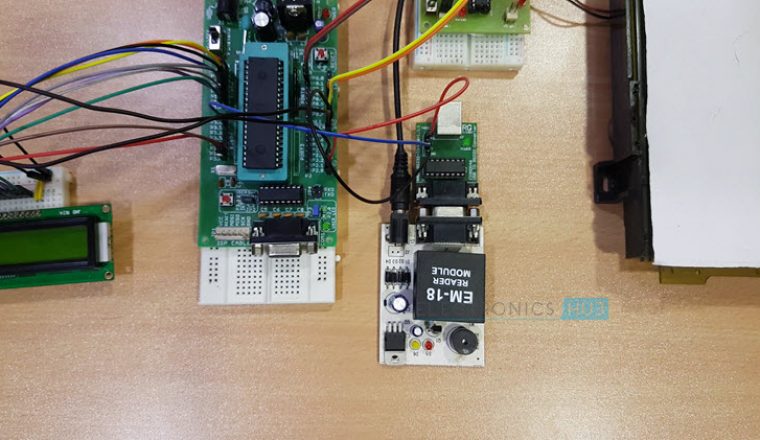
The most commonly used RFID reader is EM-18 reader module. This module has a built in antenna which is used to power the RFID Cards and also extract the information from the Card’s microchip.
“Also read this interesting post: RFID based Attendance System
Circuit Design
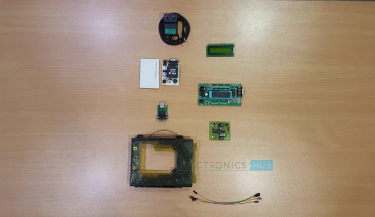
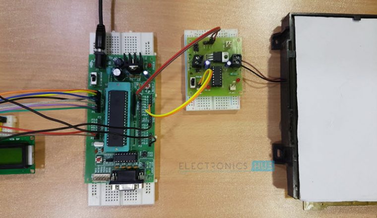
The main components of our project are Microcontroller, RFID Reader, RFID Cards or Tags, an LCD display, L293D Motor Driver IC and a Motor.
For the microcontroller to function properly, we need to connect an 11.0592 MHz oscillator along with two ceramic capacitors of capacitance 33pF to the microcontroller.
Pin 31 of the microcontroller i.e. EA Pin is connected to 5V using a current limiting resistor of resistance 10KΩ.
In order to reset the microcontroller, the RST pin (Pin 9) must be momentarily connected to 5V. Hence, a combination of push button, 10KΩ resistor and 10µF capacitor is used in the reset circuit.
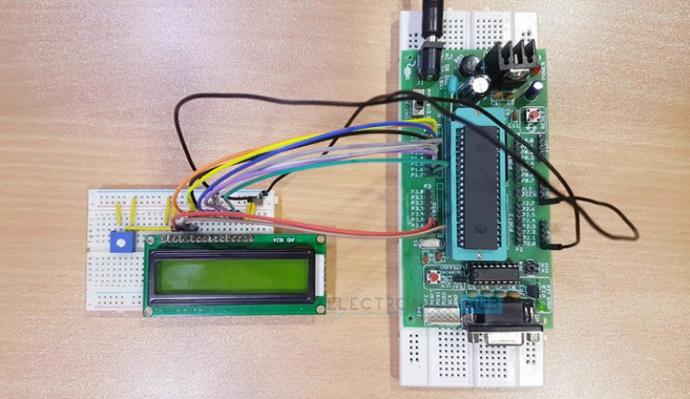
An LCD Display is used in this project to display the details of the card. The data pins of the LCD are connected to PORT1.
The control pins are connected to P3.6, GND and P3.7 and a 10KΩ potentiometer is connected to adjust the contrast.
The next component we need to connect to the microcontroller is the RFID reader module. The communication between the Reader and the microcontroller is using UART protocol.
Hence, we need to use the TX and RX pins for communication. Connect the RXD pin (Pin 3.0) of the microcontroller to the TX pin of the RFID Reader module.
Similarly, connect the TXD pin (P3.1) of the microcontroller to the RX pin of the RFID Reader module.
Finally, we need to connect the motor driver IC to the PORT0 of the microcontroller.
An important note is that Port 0 pins must be externally pulled high in order to use them as input / output pins.
Connect the two input pins of the motor driver i.e. IN1 and IN2 (Pins 2 and 7) to Port 0 pins i.e. P0.0 and P0.1 of the microcontroller. A motor is connected to output pins of the motor driver.
Complete Project Course with CODE: RFID Security Access Control System
How RFID Security Access Control System Works?
The aim of this project is to design an RFID based security access control system using 8051 microcontroller, in which only authorised personnel are allowed access to a secure area. The working of the project is explained here.
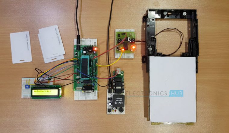
When the circuit is powered ON, the microcontroller will initially display a message as “Swipe the Card” on the LCD display.
When the RFID Card or Tag is swiped against the RFID reader, it will detect the ID card and sends the unique card no. to the microcontroller via serial terminal.
With the help of suitable programming, we need to compare the received card no. with the numbers that are already stored in the microcontroller or any database like external memory unit.
If the received number is matched with the already stored number, then the microcontroller will display the name of the card holder on the LCD and activates the motor driver IC. As a result, the door is opened for a predefined duration after which the door is automatically closed.
If there is no match for the received numbers with the stored numbers, then the microcontroller will not open the door and displays a message as “Access Denied” on the LCD display.
DOWNLOAD PROJECT CODE
Advantages and Applications
- RFID based Security Access System is designed in this project. As the system uses RFID Technology based identification, it can be used to access secured areas like research centres, defence sites etc.
- It is a low power system and also the RFID Cards or Tags used are of passive type.
Limitations
- Even though RFID Technology is secure, the security can be increased by integrating other security measures like facial detection, finger print scanner etc.
- As the card details are stored in the microcontroller, only a limited number of card details can be stored. This can be increased by implementing a memory unit like EEPROM.


3 Responses
RFID security access control system is a very good project for engineering students. further projects are expected.
Thank you for this. I have a question. From the above explanation, the only way we know that the door has been opened is from the LCD screen. Now what if i want a more practical scenario where i can integrate a maglock( electromagnetic lock) to the reader module so it can open when the card has been swiped and authenticated. Will that be possible?
I’m unable to access the program code please help me with it.
Thankyou.