RFID (Radio Frequency IDentification) is an automatic identification and data collection technology which uses the electromagnetic fields in the radio frequency range for non-contact operation.
RFID Technology is similar to that of bar codes or magnetic strips i.e. they all provide unique identification system. The data retrieving operation is also similar to the other two technologies. Bar codes and magnetic strips must be scanned against their corresponding readers and similarly RFID devices must also be scanned or swiped against their readers.
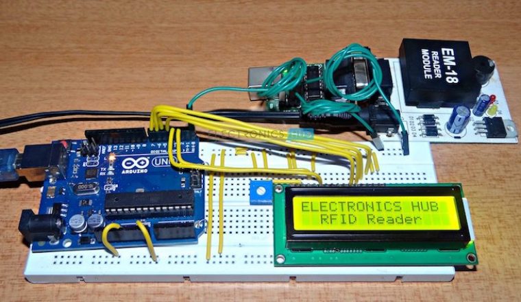
Arduino RFID Reader
The advantage of RFID technology over bar codes or magnetic strips is that RFID doesn’t need any physical contact as in case of magnetic strips (ATM or credit cards) or needn’t be placed in a particular position as in case of bar codes.
In this project, an Arduino UNO board is integrated with an RFID Reader Module in order to process the data or information retrieved from the RFID Card or Tag.
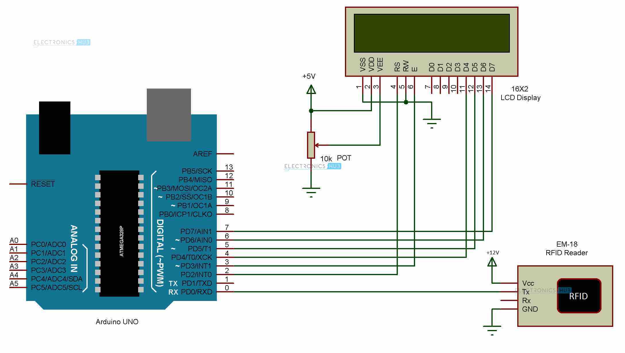
Arduino RFID Reader Circuit Diagram
Components
- Arduino UNO [Buy Here]
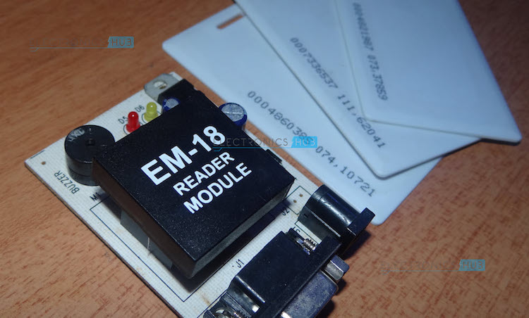
- EM – 18 RFID Reader Module
- RFID Cards or Tags
- 16 x 2 LCD Display [Buy Here]
- 10KΩ Potentiometer
- Connecting wires
- Power supply – 5V and 12V
- Prototyping board
RFID Reader and RFID Cards
As mentioned earlier, RFID is a wireless, non-contact type technology. Hence, it contains two components: RFID Cards or Tags and RFID Reader.
RFID Reader Modules are basically radio frequency transceiver (transmitter and receiver). A simple RFID reader consists of an antenna, demodulator, data decoder unit and some filters. RFID readers can read and/or write data in to the RFID cards (depending on the type of the card).
The RFID Reader module used in this project is EM – 18. It radiates a 125 KHz signal through its antenna and hence a similar frequency based RFID Card must be used.
RFID Card or Tag consists of an antenna and an IC for storing the data. RFID Cards can be either active type or passive type.
Active RFID Cards:
- They need external power i.e. they are powered by battery.
- Data can be read or write from the cards as they consists of EEPROM.
- The range is typically 100 feet or more.
Passive RFID Cards:
- Do not need external power. The required power for the operation is drawn from the electromagnetic field generated by the RFID reader.
- Usually, passive RFID cards are read only type i.e. data, which is programmed by the manufacturer, can only be read by the reader.
- The range is very small i.e. a maximum of 10 feet.
Design of Arduino RFID Reader Circuit
The main components of the project are Arduino UNO, RFID Reader, some RFID cards and an alphanumeric LCD display. The design of the circuit is described here. As Arduino is the main processing device, all the connections are the connections are explained with respect to it.
The RFID Reader module used in the project i.e. EM – 18 consists of 4 pins: Vcc, TX, RX and GND. As this module runs on 12V, it must be powered separately using a 12V supply.
Note: The power supply to the RFID Reader is dependent on the type of the module.
The communication between the RFID Reader and external devices like microcontrollers is implemented using UART protocol (hence, TX and RX pins). As the reader reads the information from the card and transmits to the host device i.e. Arduino UNO, the TX pin of the Reader must be connected to RXD pin (Pin 0) of Arduino.
Note: While programming the Arduino, the RXD pin must be disconnected as this line is used by the USB communication. To avoid this, we can define any of the other pins as serial communication pins (Rx and TX) using software and the library used for this is “SoftwareSerial.h”.
An LCD is used to display the information that is retrieved from the RFID Card. We need to connect RS, E, D4, D5, D6 and D7 pins of the LCD to Arduino. All the connections are shown in the circuit diagram.
All the other connections with respect to LCD i.e. contrast adjusting potentiometer, power supply etc. are also shown in the circuit diagram and are self-explanatory.
Working Principle of the Project
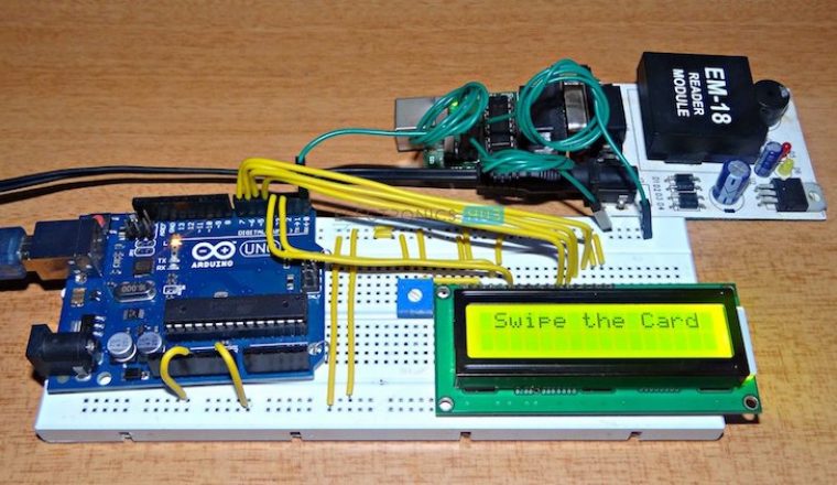
The aim of the project is to transmit the data read by the RFID reader to Arduino and display it on the LCD. The working of the project is explained in this section.
As the RFID system used here is of passive type, the information on the RFID Cards is preprogrammed. In order to read that data, the card must be brought in proximity of the reader.
The RFID reader module continuously emits electromagnetic radiation in the form of radio waves at a frequency of 125 KHz. When a passive RFID card is brought near this field, due to the concept of mutual induction, the electromagnetic field from the reader induces a small current in the antenna coil of the card.
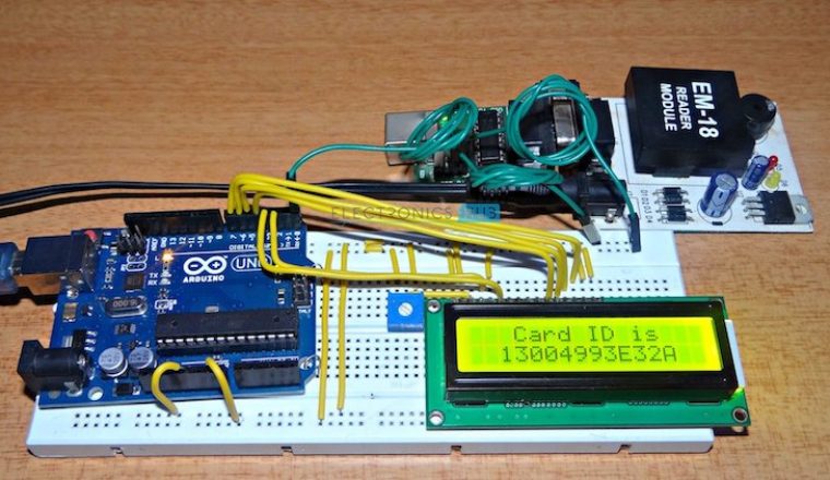
As a result, the IC in the card gets sufficient power from this and transmits the data through the antenna which is in turn received by the antenna of the reader.
The data received by the RFID reader is now transmitted to Arduino UNO using UART communication protocol. Arduino in turn displays this message on the LCD.
Applications of Arduino and RFID Integration
- The project explained here only retrieves the information from RFID card and displays it on the LCD.
- Many advanced applications can be implemented using Arduino and RFID.
- Some of the applications are RFID based authentication system, security access system, attendance system, inventory management, livestock management etc.

5 Responses
Please help me to get the link in which i can download RFID reader library for proteus. I’m waiting your response. Thank you.
I think there is no library for RFID Module in Proteus.
what is the extension for the project code
Arduino Sketches are usually saved with an extension “.ino”
Hey cool project. Can you tell me what the program for the Arduino Nano with i2c display must look like?
greeting