In this project, we will learn about the BH1750 Ambient Light Sensor Module and also how to interface a BH1750 Ambient Light Sensor with Arduino to obtain the ambient light data and display is on an LCD.
Introduction
Light Sensors are one of the important features in several devices like Mobile Phones, cameras, Cars, TVs, etc. In mobile phones, the ambient light sensor is responsible for automatically adjusting the brightness of the display depending on the intensity of the light.
In cars, ambient light sensors help in automatically turning on the headlights when outdoor lighting conditions become dark.
We have already seen few Light Sensors implemented in Electronics Hub and the simplest of all is the LDR (Light Dependent Resistor). Using an LDR is well and good if your application is very simple, like turning on a Lamp when it becomes dark.
But for complex applications like Mobile Phones, you need accurate measurement of the intensity of the surrounding light.
So, in this Arduino DiY Project, we will interface a simple Ambient Light Sensor with Arduino and extract the intensity of illuminance in lux (lx).
Output Video
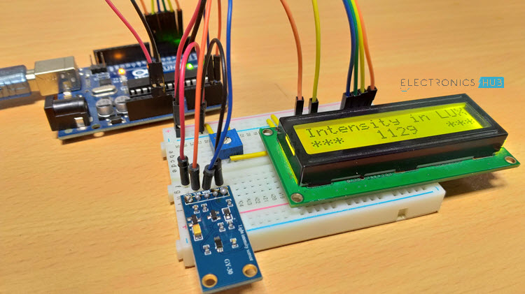
The following video shows the output of the project.
A Brief Note on BH1750 Ambient Light Sensor
The BH1750 Ambient Light Sensor Module is based on the digital Ambient Light Sensor IC BH1750FVI developed by ROHM Semiconductor. It is a digital IC with built-in 16-bit illuminance to digital converter.
For communication with external devices like Microcontrollers, the BH1750 Ambient Light Sensor IC uses I2C Bus Interface.
The following is the image of a typical BH1750 Ambient Light Sensor Module available today.
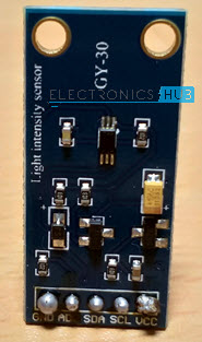
Some features of this BH1750 Ambient Light Sensor are mentioned below.
- I2C Interface
- Wide range – 1 – 65535 lx
- Built-in A to D Converter where Illuminance is the Analog Input
- Small influence of IR Radiation
- Very minimum external components
- Two devices can be connected on the I2C bus
Pin Configuration of BH1750 Ambient Light Sensor
The BH1750 Ambient Light Sensor Module has 5 pins on it. The following image shows the pins of this sensor.
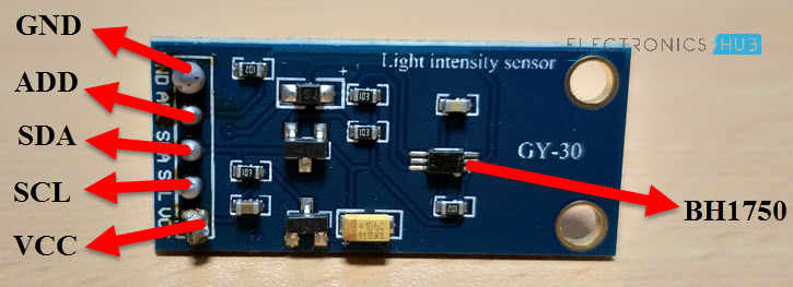
Pin Description
- VCC – 3.3V to 5V
- GND – GND
- SCL – I2C Clock
- SDA – I2C Data
- ADD – I2C Device Address
Interfacing BH1750 Ambient Light Sensor with Arduino
By interfacing BH1750 Ambient Light Sensor with Arduino, you can measure the ambient light data and use it in any application like turning on a street light or night lamp.
Since the BH1750 Ambient Light Sensor interfaces over I2C bus, we have to use the I2C pins of the Arduino.
In case of Arduino UNO, Analog Pins A4 and A5 are the I2C Bus pins where A4 is SDA and A5 is SCL.
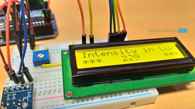
The output of the BH1750 Ambient Light Sensor is displayed on a 16×2 LCD Display that is interfaced with Arduino.
Circuit Diagram of BH1750 Ambient Light Sensor with Arduino
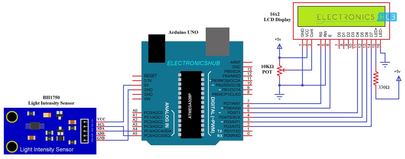
The following image shows the circuit diagram of Interfacing BH1750 Ambient Light Sensor with Arduino UNO.
Components Required
- Arduino UNO
- BH1750 Ambient Light Sensor Module
- 16×2 LCD Display
- Mini Breadboard
- 10KΩ Potentiometer
- 330Ω Resistor
- Connecting Wires
Circuit Design
First, connect the VCC and GND of the BH1750 Light Sensor to +5V and GND of Arduino. Then connect the SCL and SDA pins of the sensor to corresponding pins of Arduino (A5 and A4).
The ADD Pin can be left open but you can connect it to GND. This makes the ADD Pin LOW and the I2C Slave Address of the BH1750 Ambient Light Sensor becomes 0x23. This is important in programming.
NOTE: If the ADD Pin is made HIGH, the I2C slave address of the BH1750 Ambient Light Sensor will be 0x5C. So, two BH1750 Ambient Light Sensors can be connected to the same I2C Bus where one ADD Pin is made LOW and the other ADD Pin is made HIGH.
Coming to the LCD, the RS, E, D4 through D7 Pins of LCD are connected to 7 through 2 Digital I/O Pins of Arduino UNO. A 10KΩ Potentiometer is used to adjust the contrast of the display.
Code
The code for Interfacing BH1750 Light Sensor with Arduino is given below.
Working
Make the connections as per the circuit diagram and upload the above code. Arduino will try to extract the ambient light data from the I2C bus and after simple calculations, the result is displayed on the LCD.
Applications
The BH1750 Light Sensor can be used in various applications like
- Mobile Phones
- LCD TVs
- Notebooks
- Personal Computers
- Cars
- Portable Gaming Devices
- Digital Cameras and Video Recorders
- LCD Info Displays

5 Responses
Great invention, I can bet this will help a lot in the electronic industry.
Hi, can I know where did you purchase this light sensor?
In a local electronics store.
hi.
how can I download a schematic of bh1750 for Proteus ?!
hello, Please what is the wiring diagram is the code for 4 sensors