A Touch Dimmer Switch Circuit is a simple project, where the dimmer action is achieved with the help of a Touch Sensor. While a regular switch is used to simply turn ON or OFF a light, a Dimmer (or Dimmer Switch) will allow us to control the brightness of the light. Without a Dimmer Switch, the light bulbs tend to glow at full brightness consuming maximum power. If full brightness is not required, then Dimmer Switches can be used and save some energy. With the help of a Dimmer Switch, we can vary the brightness from fully off to fully on.
Different light bulbs need different dimmer switches and there are different types of Dimmer Switches available in the market. Some of the commonly found Dimmer Switches are Slider type and rotary type.
In this project, we have designed a Touch Dimmer Switch using Arduino. The Touch Dimmer Switch Circuit is implemented using a Touch Sensor. The circuit design, components and working of the project is explained in the following sections.
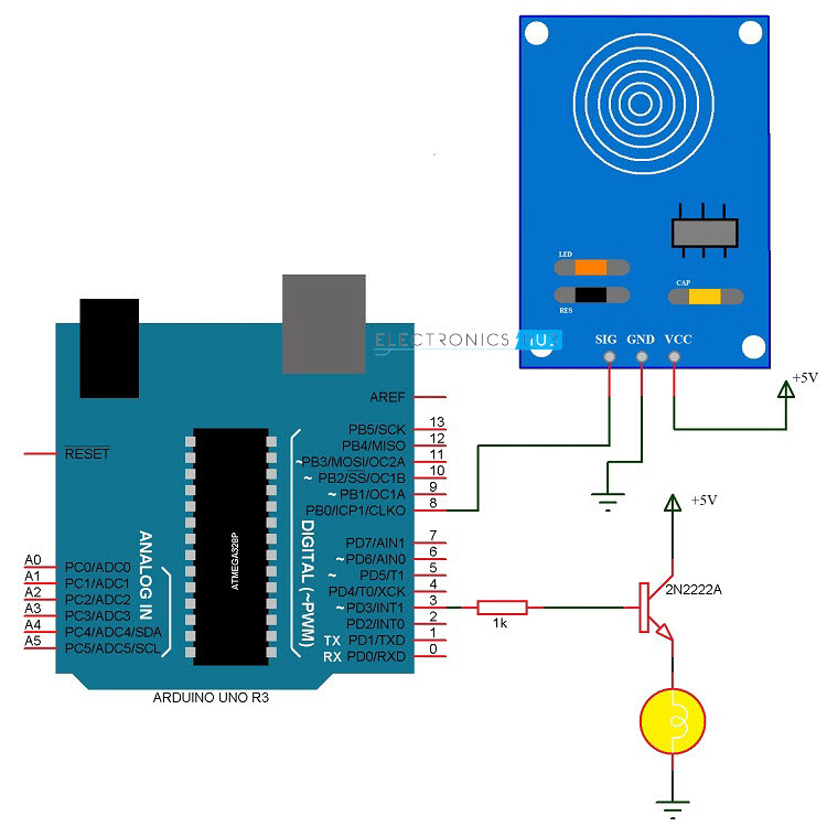
Circuit Diagram of Touch Dimmer Switch Circuit
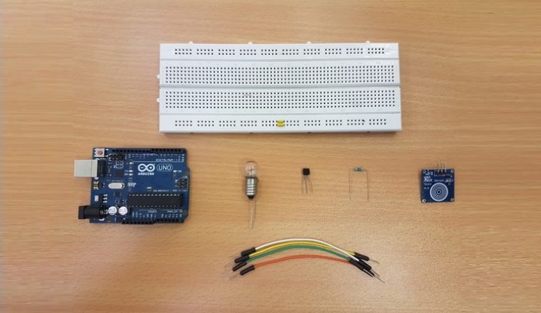
Components Required for Touch Dimmer Switch Circuit
- Arduino UNO [Buy Here]
- Touch Sensor
- 2N2222 NPN Transistor
- Small Bulb
- 1 KΩ Resistor
- Power supply
- Breadboard (Prototyping board)
- Connecting Wires
Component Description
Arduino UNO: In this project, Arduino UNO is used to detect the output from the touch sensor and correspondingly drive the bulb.
Touch Sensor: A Touch Sensor is a type of sensor that detects physical touch or proximity. They are input devices like buttons and switches but are more sensitive than those two. Hence, touch sensors are replacing buttons in devices like mobile phones and laptops.
There are different types of touch sensors like resistive touch sensors, capacitive touch sensors, piezo touch sensors etc. The most common one is the capacitive type touch sensor and we have used one in this project.
The advantage of touch sensors is that with a single sensor, we can get multiple operations like swipe, tap and pinch. The working of a touch sensor (Capacitive type to be specific) is simple.
Basically, it detects the change in capacitance of the sensor when we touch it. Additionally, some sensors can detect these changes in capacitance without the physical contact but when the finger is placed slightly near to the sensor.
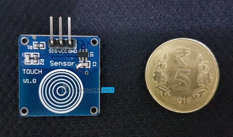
The touch sensor used in this project is based on TTP223 Touch Pad Detector IC. This particular IC can detect 1 key touch and the sensor can be used as replacement for traditional button in a wide range of consumer products. For additional information regarding the Touch Pad Detector IC and the circuit of the touch sensor, refer the datasheet of TTP223.
The output of the touch sensor will be logic HIGH when we place our finger on the touch plate. We will use this logic in the programming part of the Arduino.
How to Design Touch Dimmer Switch Circuit ?
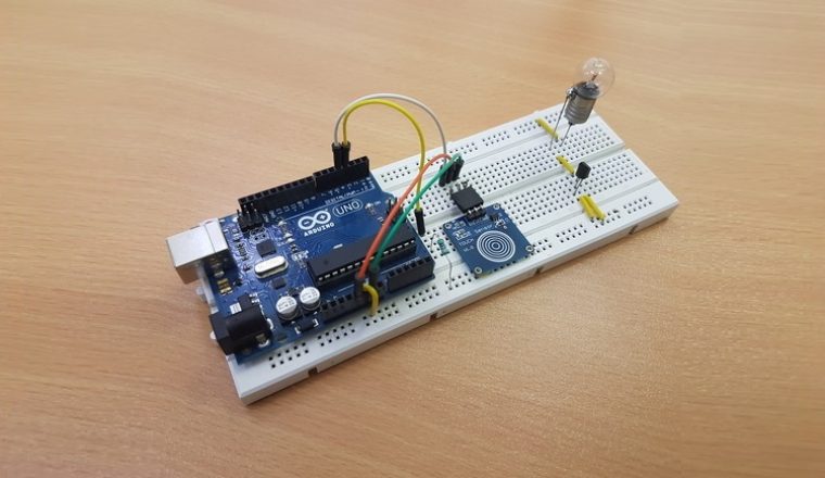
The design of the Touch Dimmer Switch Circuit is very simple and is explained here. The touch sensor is given the power supply by connecting 5V to VCC and ground to GND pins. The SIG pin of the touch sensor is connected to any of the digital input / output pin of the Arduino UNO board. Here, it is connected to digital I/O pin 8.
Next, we will connect a small incandescent bulb that glows on DC. The bulb is interface with the Arduino UNO board with the help of a transistor. So, first connect the base of a transistor like 2N2222 to any digital I/O pin of Arduino UNO with the help of a current limiting resistor.
Then connect the collector terminal of the transistor to the 5V power supply. And finally, connect a bulb between the emitter and ground terminals. This completes the design of the circuit.
Working of the Touch Dimmer Switch Circuit
As mentioned earlier, there are many types of dimmer switches for different types of bulbs. In this project, a simple touch dimmer switch circuit is designed. The working of the project is explained here.
When the sensor is not touched, the SIG pin of the sensor remains LOW. Whenever we touch the sensitive part of the touch sensor, the SIG pin of the sensor goes HIGH. Since it is connected to Arduino UNO, we will detect this change in state i.e. LOW to HIGH.
So, when the finger is placed on the touch sensor, Arduino UNO detects the change in the logic state of the sensor’s output and drive the bulb using Pulse Width Modulation (PWM). Hence, the bulb is connected to a PWM pin of the Arduino UNO.
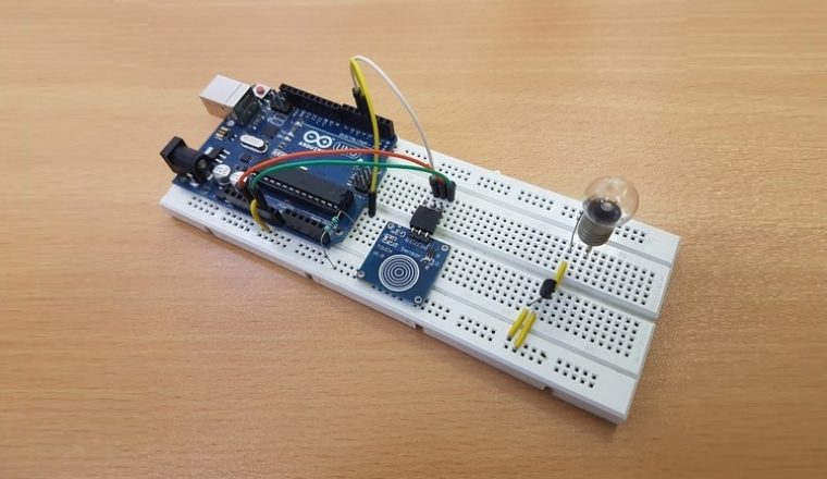
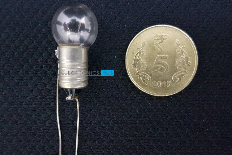
As we continue to place the finger on the touch sensor, Arduino UNO slowly increases the intensity of the bulb with the help of PWM. In the project, we used a tiny bulb as shown in the following image instead of a big incandescent bulb.
This process continues until the finger is lifted or maximum brightness is reached i.e. the bulb is fully ON. In order to decrease the brightness of the bulb, double tap and on the double tap, continue to place the finger on the touch sensor.
Arduino UNO is programmed such that, if a double tap is detected (two touches with a very small delay) it has to reduce the brightness of the bulb and thus acting as a dimmer switch.
Similar logic of PWM is used for reducing the brightness of the bulb where, when continued to place the finger on the double tap (tap once and tap and hold the finger on second tap), the intensity of the bulb gradually decreases until the finger is lifted or the bulb reaches minimum brightness i.e. it is completely OFF. This is how a Touch Dimmer Switch circuit using Arduino works.
Code
Applications
- A simple Digital Touch Dimmer Switch Circuit is implemented in this project with the help of a Touch Sensor and Arduino UNO.
- This Touch Dimmer Switch can be used to control the brightness of a bulb by simply touching the sensor.
- Can replace traditional Dimmer Switches like slide switch or rotary type switch for bulbs.
- In order to use the touch dimmer switch with AC incandescent bulbs, dedicated ICs like TT6061A can be used.
NOTE: Be cautious when using Touch Sensor based Dimmer Switch for AC incandescent bulbs.
Construction and Output Video

19 Responses
Can I know what is the software used to insert the code?
Hi, We have used Arduino IDE for writing, compiling and uploading the code.
Is this a working project
Hi, Yes. It is tested.
is this a working project?
Yes. The circuit is tested. Check out the output video here https://www.youtube.com/watch?v=6jHIxsvZNRg
Can i used Arduino Nano instead of UNO??
Yes. You can.
Hello. May I ask if I can control the dimming of the light bulb using the serial monitor of the Adruino? If yes, How can i modify the code? Thank you very much!
If instead of an incandescent lamp, an LED bulb is used…would that require a different type of dimmer?
Moreover, what is the maximum allowable power of the bulb which can be used in order not to damage the Arduino circuit with high currents?
thanks.
How can i controll a 12volt single colour led strip with this type of touch switches?
does the arduino uno board needs to be connected to the laptop while demonstrating the experiment????
No, you can use a 9v power supply as well
Hi can you help me understand that if statement why is var being incremented and what does the 255 represent
in arduino we use pseudo analog signal generated by some pin like 3 pin.. Since the dogitalto analog converter of arduino is of 8 bit so 2 power 8 gives 255, which means 0 represent 0 volt while 255 represent 5 volt and the in between ragne varies
Hi .I tried this project at home .But it couldn’t work. and i have a doubt that you have mentioned in “How to Design Touch Dimmer Switch Circuit ” that the SIG pin here is connected to pin 8 but in the video it is connected to digital pin 5. So is there something to change in coding ?
is this worked in shield motor??
please help me..
Can I connect it to my cellphone instead of laptop for uploading code? Honestly, I want to avoid computer as much as possible
Hi,what kind of battery is used in this project for 5v power supply