In this project, I will talk about LM393 Speed Sensor Module, how this module works and helps in determining the speed of a rotating object and finally I will show you how to Interface LM393 Speed Sensor with Arduino and measure the speed of a motor.
Introduction
A speed sensor is a type of tachometer that is used to measure the speed of a rotating object like a motor. I have already implemented a CONTACTLESS DIGITAL TACHOMETER but that was using 8051 Microcontroller.
There are many types of Speed Sensor like Hall-effect based sensors, Magnetoresistive Speed Sensor, Eddy Current based speed sensor, etc. In this project, I have used a pretty inexpensive Infrared based Speed Sensor.
Irrespective of the type of implementation, all speed sensor serves the same purpose: help us determining the rotational speed of a rotating object.
A Brief Note on LM393 Speed Sensor Module
In order to measure speed of a motor using Arduino, I have used an LM393 Speed sensor with Arduino. The LM393 Speed Sensor Module is basically an Infrared Light Sensor integrated with LM393 Voltage Comparator IC.
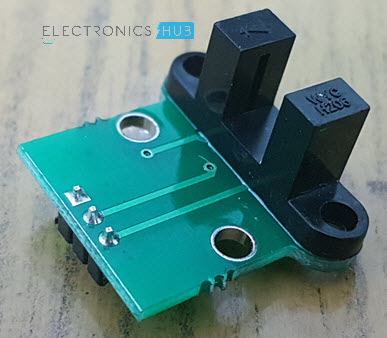
The following image shows the speed sensor module I have used.
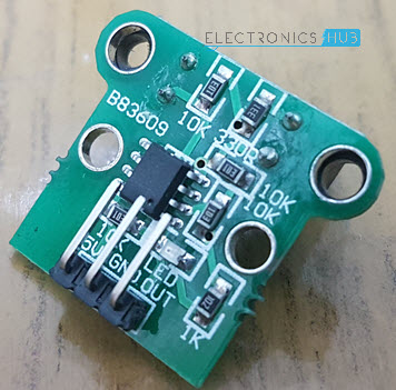
If you are familiar with the designs of sensor, then this sensor can also be divided into two parts: the sensor part and the control part.
The sensor part of the LM393 Speed Sensor module consists of an Infrared LED and an NPN Photo Transistor. These two components are placed facing each other is a special housing made of black thermoplastic.
This special housing ensures that the Photo Transistor receives light only from the Infrared LED and all the external source of light is eliminated.
Coming to control unit, it is made up of LM393 Voltage Comparator and a few passive electronic components. The signal from the photo transistor is given to the LM393 and based on the presence or absence of an object between the Infrared LED and the Photo Transistor, the Output of the LM393 IC will either be HIGH or LOW.
More details is explained in the working.
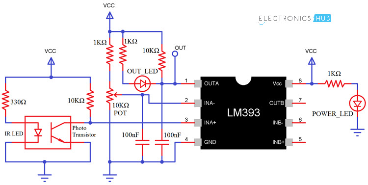
Schematic of LM393 Speed Sensor Module
If you are interested in understanding the LM393 Speed Sensor Module a little bit more, then its schematic might be helpful. The following image shows the schematic of the LM393 based Infrared Sensor that is used as a speed sensor in this project.
Interfacing LM393 Speed Sensor with Arduino
As mentioned earlier, the main aim of this project is to measure the rotational speed of a motor using an Arduino. In order to measure the speed of a rotating device like a simple DC Motor for example, we need a special device like a speed sensor.
So, interfacing an LM393 Speed Sensor with Arduino would be helpful for the project. This interface can also be useful in several robotic application that are implemented using Arduino as the main controller.
Circuit Diagram
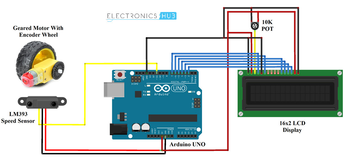
The circuit diagram for the interface of LM393 Speed Sensor with Arduino is shown in the following image.
Components Required
- Arduino UNO [Buy Here]
- LM393 Speed Sensor Module
- 16×2 LCD Display [Buy Here]
- 5V Geared DC Motor
- Encoder Wheel
- Speed Controller for Motor (Optional)
- Connecting Wires
- Breadboard
Circuit Design
First, connect the VCC and GND of the LM393 Sensor to +5V and GND of Arduino. The OUT or SIG pin of the sensor is connected to Pin 11 of Arduino.
Coming to the LCD, its RS and E pins are connected to Pins 7 and 6 of Arduino. The data pins D4 – D7 are connected to Pins 5, 4, 3 and 2 of Arduino.
Rest of the connections are as per the circuit diagram.
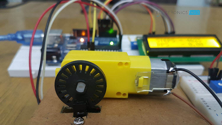
I have made a small setup with a piece of cardboard to fix the LM393 Sensor and Mount the Encoder Wheel on the top so that the wheel passes through the gap provided in the housing i.e. between the Infrared LED and NPN Photo Transistor.

The encoder wheel consists of 20 holes (this number becomes important in the program part).
Code
The code for the project how to Interface LM393 Speed Sensor with Arduino is given below.
Working
The encoder wheel (wheel with holes as shown in the image) is fixed to the geared motor and is placed in the slot of the sensor. Since the wheel is fixed to the motor, one rotation of the motor implies one rotation of the wheel.
Coming to the sensor, the Infrared LED and the NPN Photo Transistor are placed directly facing each other. When there is no object in the slot, the light from the Infrared LED always falls on the Photo Transistor.
Now, as I have mentioned that the wheel has 20 holes in it, so whenever the wheel makes one rotation, the infrared light from the IR LED is obstructed for 20 times from falling on the photo transistor.
Applications
- Robotics
- Speed Sensing
- Contactless Switching
- Printers, Scanners, Copiers
- Motor Drivers

6 Responses
very useful , thx
How can I use this to precisely control the speed of the motor?
HOW TO DO IT USING NODEMCU ESP2866
work same on range 2-36V, so esp, stmf103, … same.
I want to use this for SMT parts. I will be using the gear holes on the SMT tape block/unblock sensor to count. I will need it to count 1 for every 2 holes that pass through. Would I just need to change this line of code?
rps=(temp/20); Change to rps=(temp/2);
George
@sai, works same on 3v3 esp and stm32f103c8t6 (blue pill)
@george just count on mod 2
@author, get 40 transitions. Cnt high -> low and low-> high.