In this project, we will see the Automatic Room Lights using Arduino and PIR Sensor, where the lights in the room will automatically turn ON and OFF by detecting the presence of a human.
Such Automatic Room Lights can be implemented in your garages, staircases, bathrooms, etc. where we do not need continuous light but only when we are present.
Also, with the help of an automatic room light control system, you need not worry about electricity as the lights get automatically off when there is no person.
So, in this DIY project, we have implemented Automatic Room Lights using Arduino and PIR Sensor.
Overview
 Automatic Room Lights System using Arduino is a very useful project as you need not worry about turning on and off the switches every time you want to turn on the lights. The main components of the Automatic Room Lights project are Arduino, PIR Sensor and the Relay Module.
Out of the three components, the PIR Sensor is the one in focus as it is the main device that helps in detecting humans and human motion.
In fact, the Automatic Room Lights project can be considered as one major application of the PIR Sensor. A similar concept is being already implemented in automatic toilet flush valves, hand dryers, etc.
Also Read: ARDUINO PIR SENSOR TUTORIAL
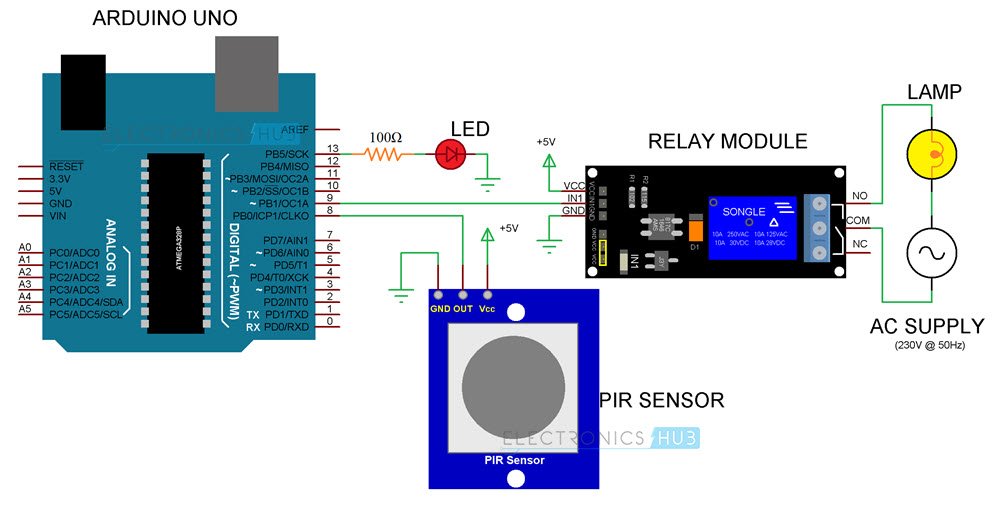
Circuit Diagram of Automatic Room Lights using Arduino
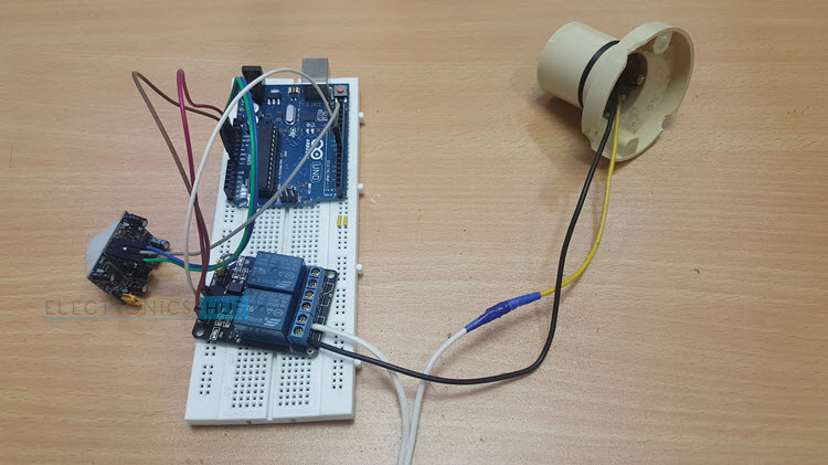
The following image shows the circuit diagram of the project implemented using Arduino UNO, PIR Sensor and a Relay Module.
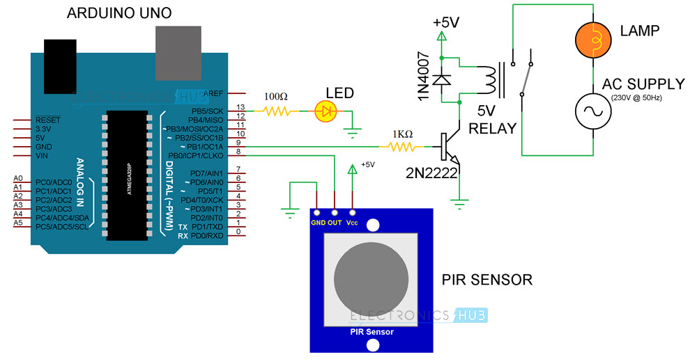
If you do not have a relay module, you can make one yourself using very simple hardware. The following circuit diagram shows the project being implemented with the help of discrete components for the Relay Module.
CAUTION: The project involves connection with 230V AC Mains (or 110V, depending on where you live!!!). Be extremely careful when connecting the bulb and Relay to mains supply. If you are unfamiliar with the connections, I strongly recommend having an adult supervision (or an expert supervision).
Components Required for Automatic Room Lights using Arduino
- Arduino UNO [Buy Here]
- PIR Sensor
- 5V Relay Module (Relay Board)
- LED
- 100Ω Resistor (1/4 Watt)
- Connecting Wires
- Breadboard
- Power Supply
If you do not have a Relay Module, use the following components:
- 5V Relay
- 2N2222 (or BC547) NPN Transistor
- 1N4007 PN Junction Diode
- 1KΩ Resistor (1/4 Watt)
Component Description
PIR Sensor
We have already seen about PIR Sensor in the PIR Motion Sensor Tutorial and also implemented in a variety of projects like Home Security System and Automatic Door Opener.
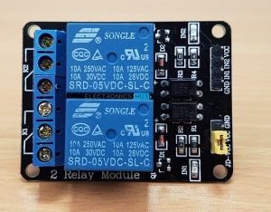
Relay Module
A Relay Module is a very useful component as it allows Arduino, Raspberry Pi or other Microcontrollers to control big electrical loads. We have used a 2-channel Relay Module in this project but used only one relay in it. The relay module used in this project is shown below.
In order to control a single relay on the board, we need to use three pins of the relay module: VCC, GND and IN1.
Before continuing, read How to use 5V Relay on Arduino
NOTE: The relay module used in this project is as active LOW one i.e. when the IN1 pin is HIGH, the relay is OFF and when it is LOW, the relay is activated. This point is important while programming the Arduino UNO.
Circuit Design
PIR Sensor’s Data OUT Pin is connected to Arduino’s Digital I/O Pin 8. An LED is connected to pin 13 of Arduino to indicate whether the light is turned ON or OFF.
The IN1 pin of the Relay Module is connected to Pin 9 of Arduino. A bulb is connected to mains supply through relay. One terminal of the bulb is connected to one wire of the mains supply. The other terminal of the bulb is connected to the NO (Normally Open) contact of the Relay Module.
COM (Common) contact of the Relay is connected to the other wire of the mains supply. Be careful when connecting this part of the project.
Code
The code for the Automatic Room Lights using Arduino and PIR Sensor is given below.
Working of the Project
The Automatic Room Lights using Arduino and PIR Sensor is a simple project, where the lights in the room will automatically turn on upon detecting a human motion and stay turned on until the person has left or there is no motion.
Working of this project is very simple and is explained here.
Initially, when there is no human movement, the PIR Sensor doesn’t detect any person and its OUT pin stays LOW. As the person enters the room, the change in infrared radiation in the room is detected by the PIR Sensor.
As a result, the output of the PIR Sensor becomes HIGH. Since the Data OUT of the PIR Sensor is connected to Digital Pin 8 of Arduino, whenever it becomes HIGH, Arduino will activate the relay by making the relay pin LOW (as the relay module is an active LOW module).
This will turn the Light ON. The light stays turned ON as long as there is movement in front of the sensor.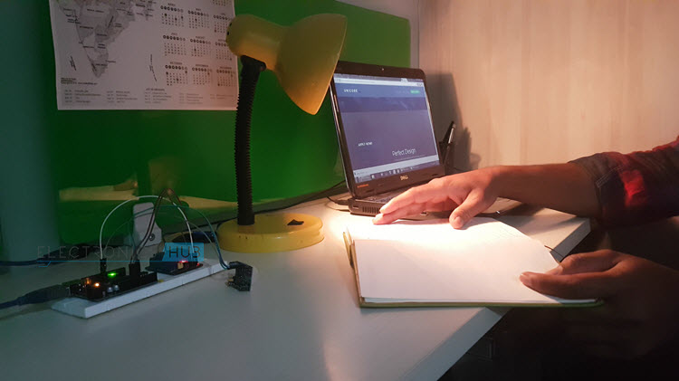
If the person takes a nap or leaves the room, the IR Radiation will become stable (there will be no change) and hence, the Data OUT of the PIR Sensor will become LOW. This in turn will make the Arduino to turn OFF the relay (make the relay pin HIGH) and the room light will be turned OFF.
Applications
I’ve already mentioned a few applications of the Automatic Room Lights concept. Some of them are:
- Garage Lights
- Bathroom Lights
- Hand Dryers
- Toilet Flushers
- Security Lights

54 Responses
I like your project.
Can u please tell how to program arduino uno .please send the respective instructions or related vedio to program an arduino uno.
nice project very useful as
excellent project
showing an error that ‘lWrite’ was not declared in this scope
Sorry. It was a typing mistake. It should be digitalWrite. I’ve made the changes. Thanks for sharing.
Bro can you please demonstrate this project by making a video on your YouTube channel
Nice project, however would it not be useful to connect an light resistor, so that the light only turn on when it’s dark?
Can we use more than one light using this curcuit or we can use only one light
Hi,
You can use more number of lights. Just connect a higher channel Relay (like an 8-channel for 8 lights) and modify the code accordingly.
Dear sir
Can u write code for 4 lights ?? I want 4 lights to control
And a ckt diagram please help me with this
Is the code complete? Cause I have tried running this project on proteus and it’s not working.
Yes. The code is complete and tested.
1. if we replaced the light with small portable fan, does it work out?
2.can we use the same code for 1 chanel only for the relay module?
Yes and Yes.
What is right system arduino
Great project Ravi, thanks.
I am however struggling to understand your use of millis() as I dont see why you have tied the on/off to the length of time the Arduino board has been running the current program or am I just being dumb?
Also have you any suggestions on how to change the program to delay the off signal for say 10 (or perhaps 30) seconds after the PIR detects no motion. That way the cupborad light where I will be using the sketch will stay on until the door is closed then turn off the light.
Hope it is OK to ask this of you.
Les
can i use 12v relay for this project
Only 5V relay.
Why
Actually , I tested on proteus but cannot working. But I have made connection between Input of Relay and Output of PIR and it working. And I changes the coding from Sensor = 8, to sensor = 9 and changes the circuit wire ofoutput sensor connect to input of relay and connect to arduino at 8. It working. So , maybe it does not working bexause no connection between PIR and relay . so nothing happen. Thank You
What is the concept of this project?
Another way to do this is to use an active high relay module and forget about the arduino. Just take the output of the PIR and tie it to the 1k resistor before the 2N2222.
That the simplest way to implement this idea. But with Arduino (or any other controller) you can really control the IO.
Please I need to study the operation of the project, How will I get the full materials how will I get it.
nice project,i ran it and added to the application 2 more lights lighting in sequence..application for a one way corridor..thank you..now trying to figure out how to change or alter the sensitivity of the sensor.
thanks for knowledge…
Where is the code ?
Hi,
Code is uploaded. Check at the bottom of the post.
how much this cost?
HI.
i make this project, but my PIR sensor is not working. please solve my proplem.
Thanks
Sir ,
How to replace a lamp with led panels (in intension on saving power) ,,with this ac supply
Great project. My wife no longer complains that I leave the lights in my shop ON.
I used a At-tiny instead of the Adruino. Minor changes to the code to accommodate the tiny.
How much did you invest for the project . And for what price would you sell it out in public . Let me know . Thanks .
I need an improvised version, Is it possible to make it such that you load times for it to turn off and on the lights? I want to use it for a poultry farm where I cannot be there all night to turn on and off the lights according to a schedule. I will really appreciate your input.
Hello sir
I m interested in this project plz suggest me how I make this and what about it’s cost and construction plz sir
How much it will cost?
I liked the project. Thank you very much for the knowledge.
the project is very nice and useful. can u plzz mention some logical usefulness of this project plzz??
I made connecion as per your suggestion but o/p was no come correct
i am running same code but problem for output pls help what exact problem
What if I use PIR Motion Sensor Grove? What changes should i do?
Thanks for this project. I will try it
Please, what modifications would be necessary to implement this for a row of lights which aren’t simply connected together…. say a system in which each light in a row turns on when you come under it and turns off 5 seconds after you’re away from it and each of the lights behaves that way independently of the rest? How many microcontroller or relay modules will I need? One for each bulb(which would be too expensive)? Please I’m new to microcontrollers so I don’t know the possibilities and limitations of the devices is why I’m asking such a funny question. Please, I need it for a school project.
I like your project very much, This project help us to made automatic light controller with pir sensor
hi… suppose if we are implementing this project into a classroom or in a big hall where single PIR is not sufficient then what measures would be taken for controlling room or hall load and is it possible that we use only single or two PIR sensors on the main door of classroom or hall and treat PIR as counter. mean when number of entrances and exits becomes equal or when there is nobody into the room, load automatically switch off.
why can’t we use a 12V relay module
I like this project please how can I get the materials
hw much time it will tke to turn on or off?
PIR sensor, as well as relay module, are connected to 5V on Arduino there is only one port for 5 V so what to do?
Use a breadboard.
Hi I have taken an inspiration out of your project and wanted to ask that is it possible to replace the light or bulb to any devices like AC?
What is the role of resistor
This project was helpful for me.
My Light Bulb is not glowing up. What should I do?