In this project, we will see how to control a DC Motor using Arduino and L298N Motor Driver. There are different ways to control a DC Motor but the Arduino DC Motor Control using L298N Motor Driver is becoming quite popular for many reasons.
Overview
A DC Motor is the simplest of motors that beginners and hobbyists encounter. It is very simple to operate: connect the two leads of the motor to the two terminals of a battery and voila! Your motor starts rotating.
If you switch the leads i.e. reverse the polarity, the motor will rotate in reverse direction. It is as simple as that.
If you want to control the speed of rotation of a simple DC Motor, then there is a technique called PWM DC Motor Control. The Pulse Width Modulation or PWM signal generated by this technique will allow us to control the average voltage that is being delivered to the DC Motor.
Speed Control of DC Motor using PWM
Using PWM technique, the average value of the voltage that is applied to the DC Motor is controlled by turning the power on and off at a very high rate. The frequency of this switching will be in the order of few tens of kilo Hertz.
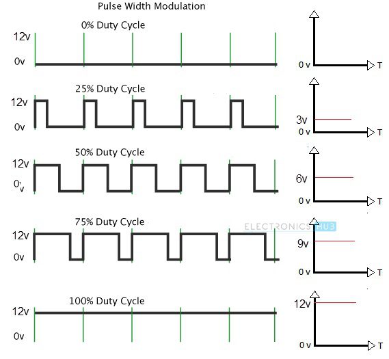
Now, the average voltage applied to the DC Motor will depend on what is called as the Duty Cycle of the PWM Signal. Duty Cycle of a PWM Signal is nothing but the ratio of the time for which the signal is ON or HIGH to the total time period of the signal i.e. sum of ON time and OFF time.
Duty Cycle is usually expressed in percent and the following figure represents different PWM Signals of a 12V supply with different duty cycles of 0%, 25%, 50%, 75% and 100% respectively.
Now that we have controlled the average voltage that is to be supplied to a DC Motor, how do we apply this voltage to the motor? Here comes the use of Transistor.
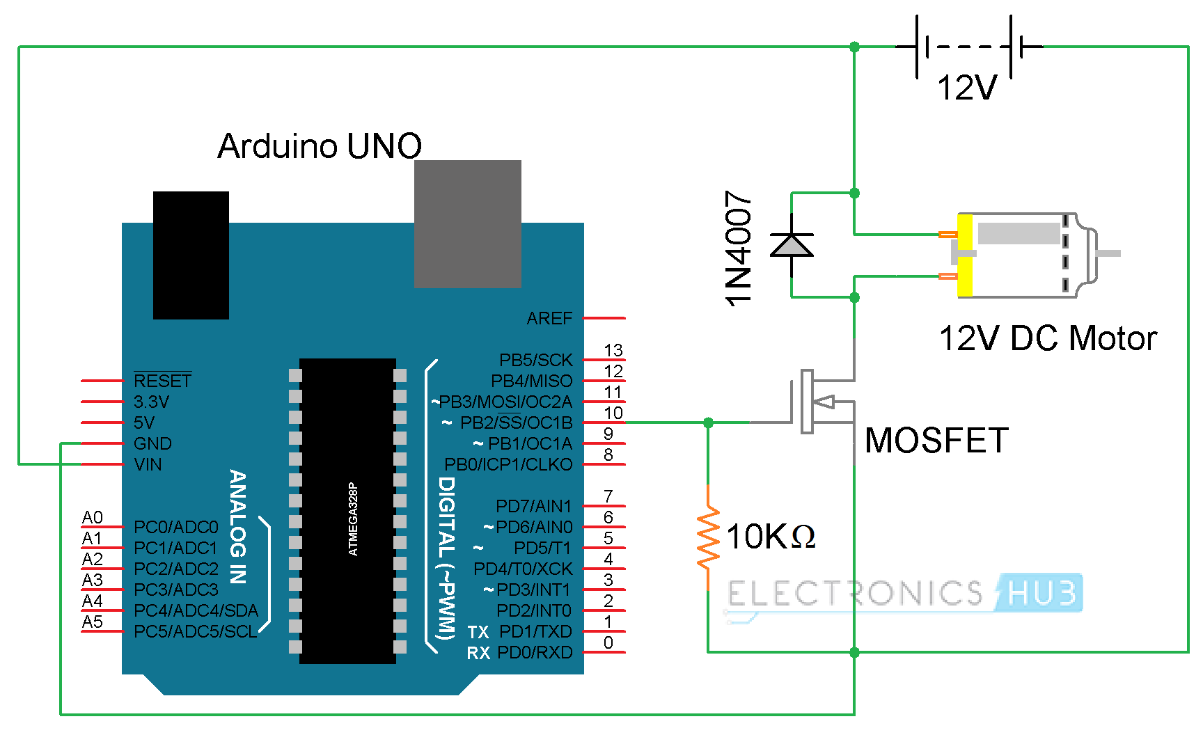
The PWM Signal from any source like Arduino in this example, can be given to the gate of a MOSFET and depending on the duty cycle of the PWM Signal, the speed of the DC Motor will vary.
The following image shows a simple circuit diagram, where a PWM output from Arduino is given to a MOSFET and the 12V DC Motor is connected through the MOSFET.
The code for this circuit is given below. Using this code, the Arduino will vary the speed of a DC Motor in a fading fashion i.e. gradually increases the speed to peak and then gradually decreases the speed to halt.
Code
This circuit is good for controlling the speed of the motor but not an effective way to change the direction of rotation. For changing the direction of rotation without reversing the leads of the motor every time, you need to use a special circuit called H-Bridge.
DC Motor Control using H-Bridge
An H-Bridge is a simple electronic circuit consisting of four switching elements like transistors (BJT or MOSFET) that can drive a motor in both the directions without switching the leads.
The name “H-Bridge” refers to the look of the connection consisting of four transistors and a motor in the center forming the letter “H”.
A simple H-Bridge connection using four transistors and a motor is shown below. By activating two particular transistors at the same time, we can control the flow of current through the motor and hence the direction of rotation.
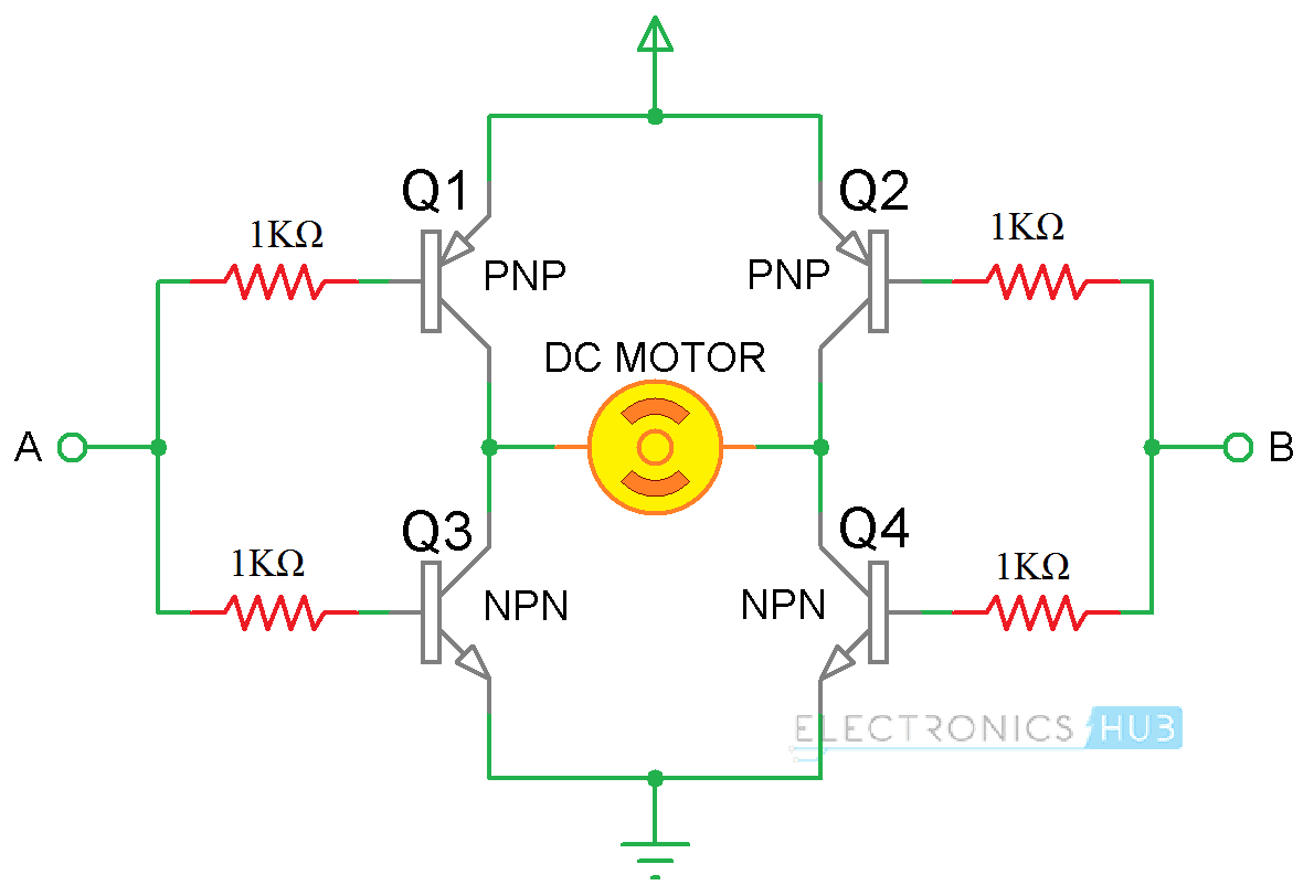
The two control inputs A and B in the above circuit will determine the direction of rotation of the motor. If A is LOW and B is HIGH, transistors Q1 and Q4 will be turned on and allow current to flow through the motor in a particular direction.
If the control input A is made HIGH and B is LOW, then transistors Q2 and Q3 will turn on and the flow of current through the motor is reversed and so the direction of the rotation.
By combining both the features i.e. PWM technique for speed control and H-Bridge connection for direction control, you can have a complete control on a DC Motor.
It is tedious to use transistors for making an effective H-Bridge connection. For this purpose, there are dedicated H-Bridge Motor Driver IC available in the market and the two common IC’s are L293D and L298N.
We have already seen how to control the speed of a DC Motor using L293D in an earlier project. In this project, we will focus on the more advanced L298N Motor Driver and see Arduino DC Motor Control using L298N Motor Driver using PWM technique.
Also read DC MOTOR CONTROL WITH ARDUINO AND L293D
A Brief Note on L298N Motor Driver
L298N Motor Driver IC is a 15-lead high voltage, high current Motor Driver IC with two full bridge drivers. The logic levels of L298N IC are compatible with standard TTL and IC can be used to drive different inductive loads like DC Motors, Stepper Motors, Relay, etc.
The following image shows the Pin Diagram of the L298N IC in Multiwatt Package (Multi Leaded Power Package).
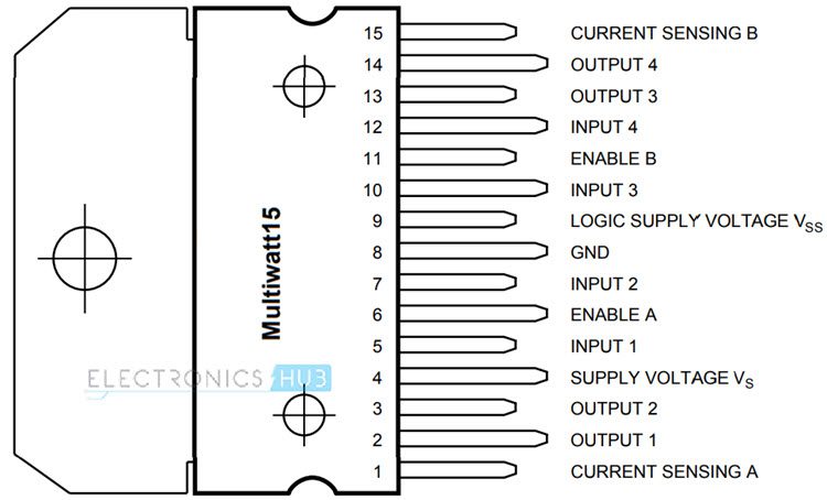
Since the L298N Motor Driver IC is a dual full bridge driver IC, you can control two motors at the same time with individual inputs. The logic supply voltage is 5V but the motor supply voltage can be as high as 45V. The peak output current per channel is 2A.
Generally, L298N Driver is available as modules that contains all the necessary components and connectors for controlling two DC Motors. One such module is shown below. I’ll explain few important components on this module.
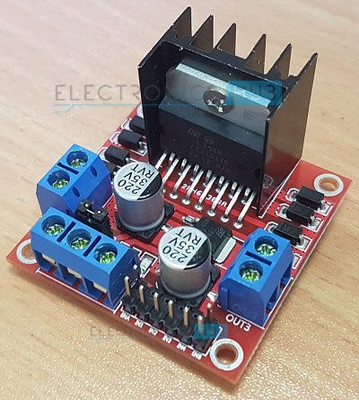
The L298N Motor Driver Module consists of two 2-pin screw terminal blocks for connecting two motors. It also has six pin male headers for connecting the two enable inputs and the four input pins (two for each motor).
There is a 3-pin screw terminal block through which you need to give the supply voltage to the motor. If the motors used are rated for 12V or less, then the 12V supply is given through this screw terminal and the onboard 5V regulator will provide the 5V logic supply to the L298N IC.
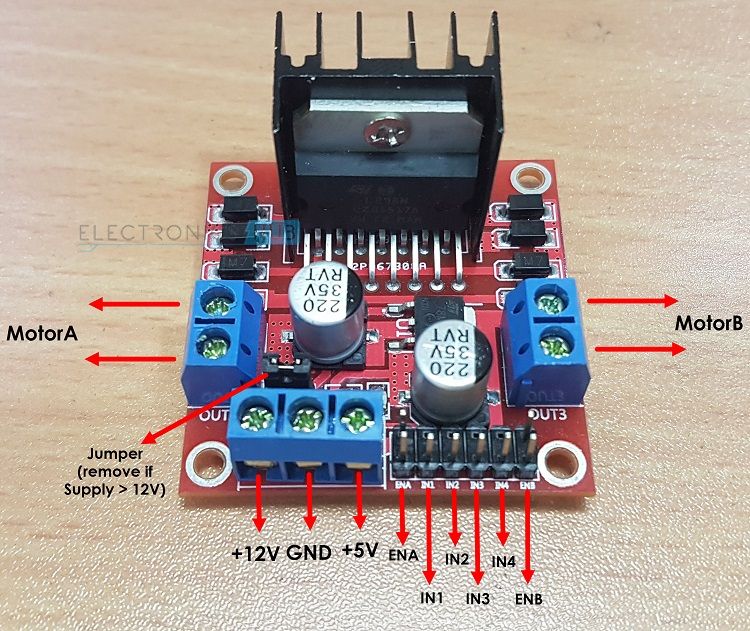
You can also access this regulated 5V through the third pin in the 3-pin screw terminal block. The jumper provided near the 3-pin screw terminal must be engaged for supply voltages up to 12V as this jumper will enable the onboard regulator. The 5V output from the third pin of the 3-pin screw terminal is available only when the jumper is engaged i.e. supply voltage is 12V. This 5V output can be used to power your Arduino Board.
If the supply voltage is greater than 12V, then remove the jumper as it might damage the regulator. In this case, the logic supply of 5V to the L298N IC is given through the third pin of the 3-pin screw terminal.
Arduino DC Motor Control using L298N
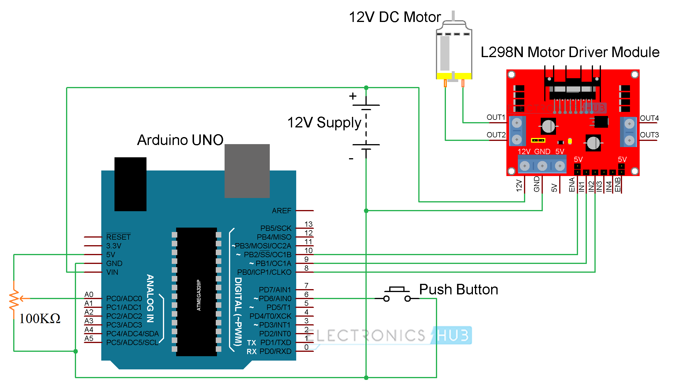
We will now see a simple circuit where we control the speed and direction of a DC Motor using Arduino and L298N IC. You need few additional components for this project and the complete list is given below. In the Arduino DC Motor Control using L298N Project, we will control both the functionalities of a simple DC Motor i.e. speed and direction of rotation using a combination of PWM Signal and L298N (H-Bridge).
Circuit Diagram
Components Required
- Arduino UNO [Buy Here]
- L298N Motor Driver Module [Buy Here]
- 12V DC Motor
- 100KΩ Potentiometer
- Push Button
- 12V Power Supply
- Breadboard
- Connecting Wires
Code
Applications
- Arduino DC Motor Control using L298N Motor Driver project can be the beginning step of many advanced projects.
- Almost all robots have wheels and we need to control the motors connected to those wheels. Hence, any Arduino based robot can implement this type of motor control using L298N.
- Some of the Robotic Applications of L298N Motor Driver are Hand Gesture Controlled Robot, Line Follower Robot, Obstacle Avoiding Robot, etc.

2 Responses
we can use this process for
-24v dc motor
– 250 watts
-current: 12A.
I am trying to use a dual pot with a center detent to control a 30A dc trolling motor. (Forward and reverse). What code can i use for this application?