In this project, we will learn about L293D and L298N Motor Drivers and also about Interfacing DC Motor with 8051 Microcontroller with the help of both L293D and L298N.
When we talk about controlling the robot, the first thing comes into the mind is controlling DC motors. Interfacing DC motor to the microcontroller is very important concept in Robotic applications. By interfacing DC motor to the microcontroller, we can do many things like controlling the direction of the motor, controlling the speed of the motor. This article describes you how to control the DC motor using AT89C51 controller (or any variant of 8051 Microcontroller).
Circuit Principle
The maximum output current of microcontroller pin is 15mA at 5V. But the power requirements of most of DC motors is out of reach of the microcontroller and even the back emf (electro motive force) which is produced by the motor may damage the microcontroller.
Hence, it is not good to interface DC motor directly to the controller. So, we use motor driver circuit in between a DC motor and the microcontroller.
Also read the interesting concept: Interfacing 7 Segment Display to 8051 Microcontroller
Here, we are using L293D and L298N motor driver ICs to drive DC motors. Using these IC’s, we can drive two DC motors at a time. For L293D Motor Driver, the motor supply is variable between 4.5 to 36V and it provides maximum current of 600mA. In case of L298N, the motor supply is up to 46V and it can provide a current of 3A.
A Brief Note on L293D Motor Driver
L293D is a quadruple H- bridge motor driver, as the name suggests it used to drive the DC motors. This IC works based on the concept of H- Bridge. H-bridge is a circuit which allows the voltage in either direction to control the motor direction.
There are 4 input pins for L293D. Motors directions depends on the logic inputs applied at this pins. EN1 and EN2 must be high to drive the 2 DC motors.
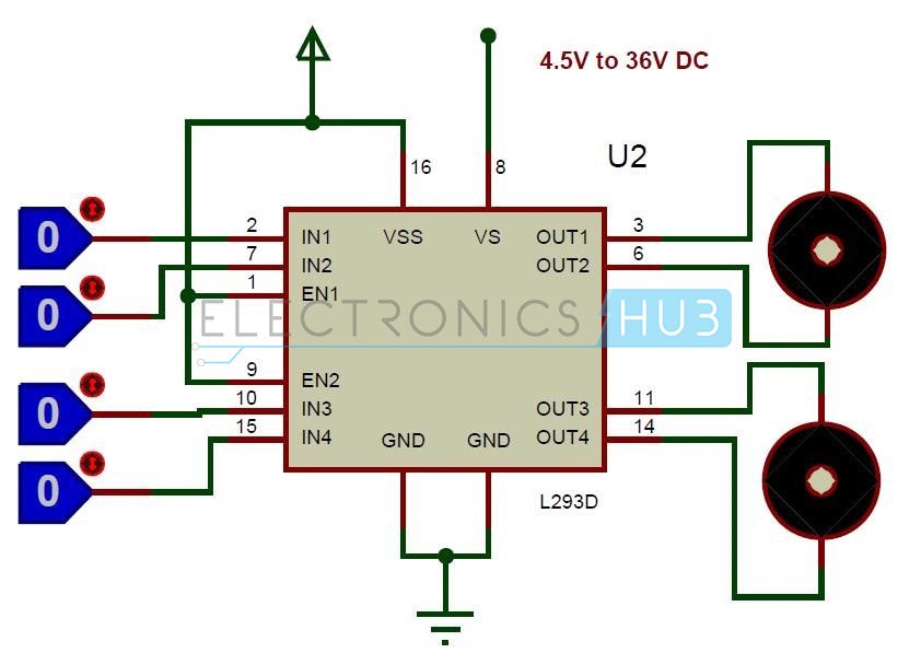
- IN1=0 and IN2=0 -> Motor1 idle
- IN1=0 and IN2=1 -> Motor1 Anti-clock wise direction
- IN1=1 and IN2=0 -> Motor1 Clock wise direction
- IN1=1 and IN2=1 -> Motor1 idle
- IN3=0 and IN4=0 -> Motor2 idle
- IN3=0 and IN4=1 -> Motor2 Anti-clock wise direction
- IN3=1 and IN4=0 -> Motor2 Clock wise direction
- IN3=1 and IN4=1 -> Motor2 idle
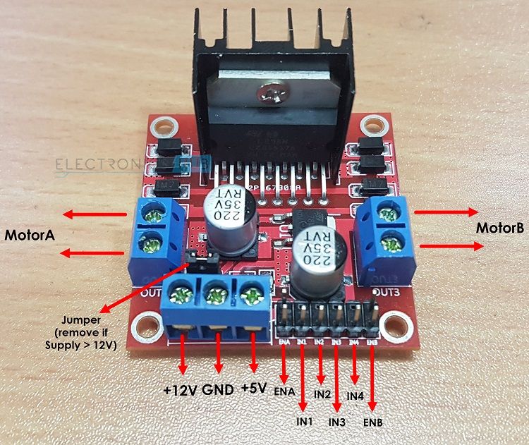
A Brief Note on L298N Motor Driver
The L298N Motor Driver Module is more frequently used driver IC’s now-a-days. The current and voltage ratings of L298N are higher than that of L293D Motor Driver.
For more information on L298N Motor Driver Module, refer to the “A BRIEF NOTE ON L298N MOTOR DRIVER“.
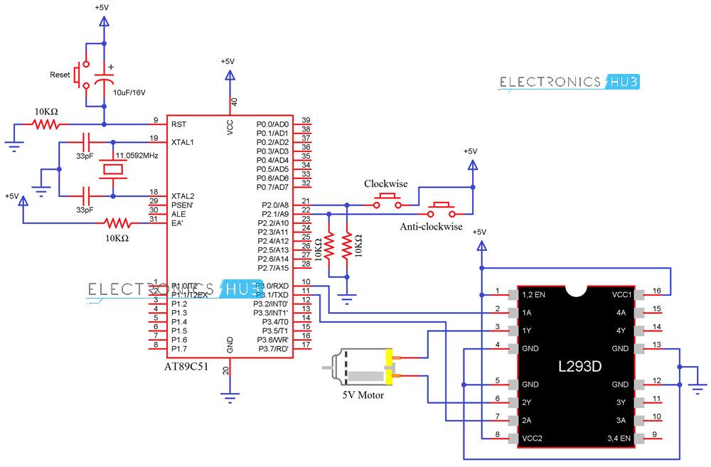
Circuit Diagram for Interfacing DC Motor with 8051 Microcontroller and L293D
Components Required
- AT89C51 (8051 Microcontroller)
- 8051 Programmer
- programming cable
- 12V DC battery or Adaptor
- L293D motor driver
- DC motor
- Electrolytic capacitor – 10uF
- 2 Ceramic capacitors – 33pF
- 10k resistors (1/4 watt) – 4
- Push Buttons – 3
- Connecting wires.
Get an idea about How PWM Based DC Motor Speed Controlling Circuit Works using Microcontroller
Circuit Design
The major components in the above circuit diagram are at89c51 microcontroller and motor driver. Here, the motor driver input pins IN1, IN2 are connected to the P3.0 and P3.1 respectively to control the motor directions. DC motor is connected to output terminals of L293D. EN1 pin is connected to the 5V DC to drive the motor.
Switches are connected to the P2.0 and P2.1 of the Microcontroller in pull down configuration. First switch rotates the motor in clockwise direction and second switch rotates the motor in anti clockwise direction. 8th and 16th pins of the motor driver are connected to the +5V supply.
Do you know How to Control Stepper Motor using 8051 Microcontroller?
Algorithm
- Declare P2.0 and P2.1 as inputs and P3.0 and P3.1 as outputs.
- Now check weather the first button is pressed or not. If pressed, then send logic one to P3.0.
- Next check whether the second button is pressed or not. If pressed, then send logic 1 to P3.1 otherwise send 0 to port 3.
Code
Circuit Simulation Video
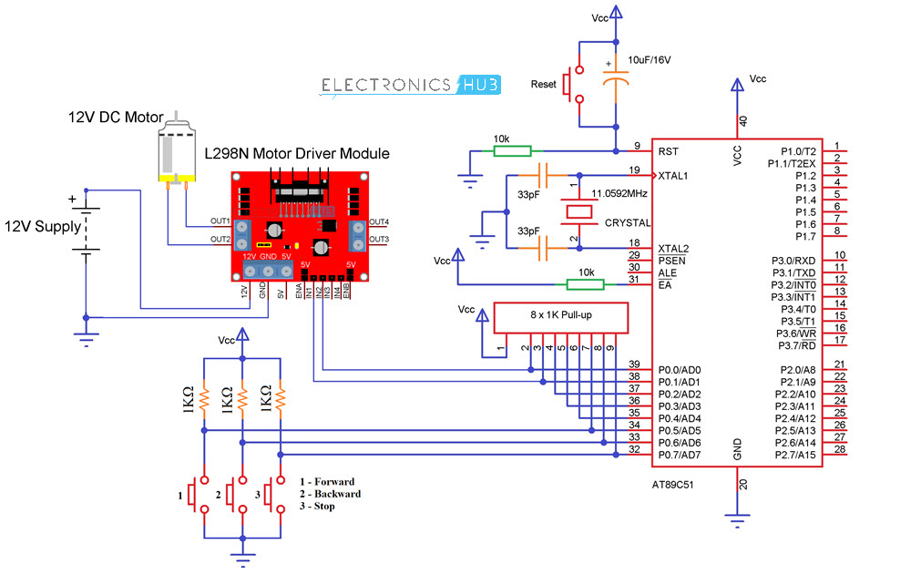
Circuit Diagram for Interfacing DC Motor with 8051 Microcontroller and L298N
Components Required
- AT89C51 (8051 Microcontroller)
- 8051 Programmer
- Programming cable
- 12V DC battery or Adaptor
- L298N Motor Driver Module
- 12V DC motor
- Electrolytic capacitor – 10µF
- 2 Ceramic capacitors – 33pF
- 10KΩ Resistor (1/4 watt)
- 1KΩ Resistors (1/4 watt) – 3
- 8 x 1KΩ Resistor Pack
- Push Buttons – 4
- Connecting wires.
Circuit Design
Similar to the above circuit, the IN1 and IN2 of the L298N Motor Driver are connected to Port 0 Pins P0.0 and P0.1 of the Microcontroller. A 12V DC Motor is conneced at the OUT1 and OUT2 terminals of the Motor Driver Module.
In order to control the Motor’s direction of rotation, I will be using three Push Buttons which are connected to Port 0 Pins P0.5, P0.6 and P0.7.
Algorithm
- Declare P0.5 and P0.6 as inputs and P0.0 and P0.1 as outputs.
- Now check weather the first button is pressed or not. If pressed, then send logic one to P0.0 and logic 0 to P0.1. This will make the motor to rotate in forward direction.
- Next check whether the second button is pressed or not. If pressed, then send logic 1 to P0.1 and logic 0 to P0.0 to rotate the motor in reverse direction.
Code
How to Operate?
- Burn the program to the 8051 microcontroller.
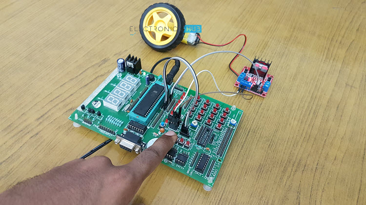
- Now give the connections as per the circuit diagrams.
- While giving the connections, make sure that there is no direct supply connection from battery to the controller.
- Switch on the board supply, now the motor is at stationary condition.
- Press first button, you can observe that motor will rotate in clockwise direction.
- Press the second button, now the motor rotates in anticlockwise direction.
- Switch off the board supply.
Applications
- This concept is used in robots to control the robot directions.
- Used to control the speed of the DC motor.
- It is used in the applications where we need to drive the high voltage motors.
Recommended Readings:

28 Responses
HELLO SIR
i would like to ask that if i have to use 3 dc motor with 8051 uc, can i use 2 l293d ic????
or is there any other option???
SUGGEST ME SIR.
THANKS….
ABDUL BASIT
to develop another project by referring the code sames like this. i try to do a robotic spry project and i need a code to drive a two motor so for this matter i just ask you this.i think your code gives me a clarity of mine project it needs simple change. and tanks for all
I want to make this project because I want to learn about robotics and this project will help me in that..and I think this project has great applications in rebotics. So please send me project code from which I will be able to make this project. Thanks
Em Actually in 2nd year Electrical Engineering. i get some help about codes because em doing work on a robotic Project. and i have Good interest in this filed. please send me these code because its my start. Thankyou
i am doing the same project for an science .. kindly send me your codes and help me out
Doing a project on microcontroller based application and for that need some help so kindly send me the code….thank you
iam doing a project named as “FULLY AUTOMATED SOLAR GRASS CUTTER” so i need the program for controlling the motor by motor driver IC and I want its program
i need your project code . because i interest microcontroller related code.
Require the code for another project.pls help.
Can you give a code for the same
Can you give the project code
Hello sir,
m trying to make an electronic duster … so i decided to connect my duster with the help of these motors… will it be possible to do so?
require it for another project. Need help !
Code is uploaded please check the article
HOW CAN I USE THIS CODE FOR KEIL ?
IT CONSIST OF LOTS OF FILE
There is a file with .c extension .Open that file and copy paste the code into keil..
Hello sir
Need code for the project based on microcontroller.
Please send me the code.
Code is provided in the article download it from there..
to develop another project by referring the code sames like this. I need your code because this code gives me idea about mine project..and actually I want to work my project on only one DC motor
Download Code from the post itself.
I want make Owen control for CNC machine . I know about. microprocessors-basic knowledge. but how make cerkit bord ? how assambl various components .how link between this component?
please help me
hi sr pleas i wena to know the use of capacitor onthe prject
Plz give me code fo dc motor interfacing..
Hai. How can I change the speed of the DC motor?
@afiq, by using mode 1 of the TMOD register, you can reload the timers register in order to change the duty cycle and produce different oscillation frequencies of motors
can the speed be varied?
Using this circuit, no!
the main two reason force us to connect motors with the microcontroller through driver