In this project, we will learn about PIR Sensor and how can it be used as a Motion Sensor through the Arduino PIR Sensor Tutorial. By going through this project, you can understand how PIR Sensor works and how to hook up a PIR Sensor to Arduino.
We have made a project using Arduino, PIR Sensor and GSM Module called GSM based Home Security System using Arduino. If you understand how a PIR Sensor works, then you can many such interesting projects and even more complex ones.
Overview
A PIR Sensor or a Passive Infrared Sensor is an electronic device that measures the infrared (IR) light emitted by the objects in its observable area. The term ‘Passive’ in the PIR Sensor indicates that the sensor actually doesn’t emit any infrared light but rather passively detects it that is emitted by its surrounding objects.
Every object, with its surface temperature greater than absolute zero i.e. -2730 C emits heat in the form of infrared radiation. Humans cannot see this radiation as the radiations are in infrared wavelength.
But PIR Sensors detect these radiations and change them into appropriate electrical signals.
Also read: GSM BASED HOME SECURITY ALARM SYSTEM USING ARDUINO
PIR Sensor
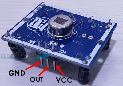
A typical PIR Sensor looks like the one shown in the image below. To connect with external devices, it has only three pins namely VCC, Digital OUT (Data) and GND.
On the top of sensor board, there is a special type of lens called Fresnal Lens that is covering up the actual Pyroelectric Sensor. The job of the Fresnal Lens is to focus all the infrared radiation onto the pyroelectric sensor.
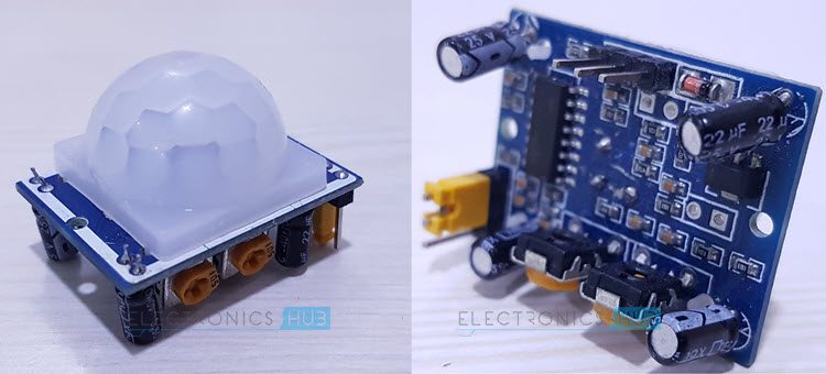
If you look at the back of the PIR Sensor board, the whole circuitry is housed there. The brain of the PIR Sensor Module is the BISS0001 PIR Motion Detector IC. Near this IC, we have two potentiometers, one for adjusting the Sensitivity and the other is for adjusting the delay time.
Using Sensitivity Adjust, you can control the range of field of view and in our sensor, it is up to 7 meters. Using the Delay Time Adjust, you can control the duration for which the Digital Out will stay HIGH when a moving object is detected.
How PIR Sensor works?
PIR Sensors are complicated than most other sensors. PIR Motion Sensor may seem simple when implemented as all you need to do is check for a HIGH signal on the Digital Out Pin of the Sensor whenever motion is detected.
But, internally, there is a lot going on and the input and output of the sensor are dependent on several variables.
The actual PIR Sensor i.e. the one which is covered with a lens, consists of two slots and both these slots are made up of IR Sensitive materials. Under normal condition where there is no movement in front of the sensor, both the slots in the Sensor detect same amount of infrared radiation.
When there is movement in front of the sensor, like a human or a cat, their radiation is interpreted by one of the slots first and the differential output between the two slots becomes positive.
As the person moves away, the second slot detects the radiation and the differential output will become negative. Based these output pulses, a motion is detected.
Testing the PIR Sensor
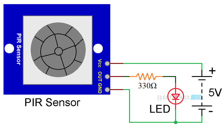
Since the Digital Out Pin of the PIR Sensor is either HIGH or LOW based on the movement detected, you can build a simple circuit to test the PIR Sensor.
The first circuit consists of a PIR Sensor and an LED. When the PIR Sensor detects motions, the LED turns ON. The duration for which the LED is ON can be adjusted with the help of Delay Adjust POT.
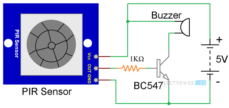
A similar PIR Sensor testing circuit is shown below but it consists of a buzzer. In order to drive the buzzer, an NPN Transistor like BC547 or 2N2222 can be used. The buzzer will be activated when the sensor detects any movement.
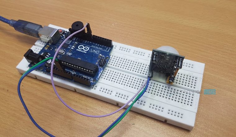
Arduino PIR Sensor: PIR Motion Sensor using Arduino
Let us make a small Motion Sensor or Motion Detector project using Arduino and PIR Sensor. In this project, the PIR Sensor detects any movement in front of it and signals Arduino. Whenever any movement is detected, Arduino will activate an alarm in the form of a Buzzer.
This circuit doesn’t implement a major design but gives an idea about how to interface a PIR Sensor to Arduino and how to can we Arduino to use the data from the PIR Sensor and drive other output devices or loads like relay, GSM Module, buzzer etc.
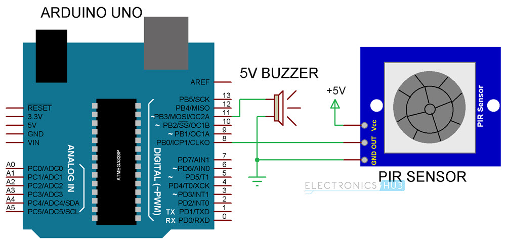
Circuit Diagram
Components Required
- Arduino UNO [Buy Here]
- PIR Sensor
- 5V Buzzer
- Breadboard
- Connecting Wires
- Power Supply
Circuit Design
The design of the PIR Motion Sensor using Arduino is very simple. The PIR Sensor Module has three pins: VCC, Digital Out and GND. Connect VCC and GND to +5V and GND respectively. Then connect the Digital Out Pin of the PIR sensor to the digital I/O pin 8 of Arduino.
As we need to indicate the detection of motion by the sensor, connect a buzzer to Pin 11 of the Arduino.
NOTE: Buzzer is connected directly to Arduino. I suggest you to connect it through a transistor as shown in the test circuit.
Code
Working of Arduino PIR Sensor Motion Detector
The working of this project is very simple. When the system is powered on, the Arduino waits for the PIR Sensor to be calibrated. The calibration period is set to 10 seconds and during this time, there should be no movements in front of the PIR Sensor.
After the calibration, the PIR Sensor will be ready to detect any movement in front of it. If the PIR Sensor detects any movements, its Digital Out pin, which is connected to Pin 8 of Arduino will become HIGH.
Arduino will detect this HIGH Signal and activates the buzzer.
Applications
- Arduino PIR Sensor Interface can be implemented in a wide range of project but the important one is the Motion Detection System.
- A variety of Home Security Systems can be implemented using Arduino and PIR Sensor.

14 Responses
Respected sir
I worked with thermionic valves, transistors, digital/anlg IC
Now my age is 70 years
I have too much interest in electronic project.
Will you please send me details know how of the ARDUINO in PDF
I will be ever grateful to you if you lecture me on know how of the ARDUINO
Wow that’s great experience. Could you please share your knowledge with students in your village. Then God will send you the pdf
Well, I am prof. Electronics.
I am pleased to help you to understand and design arduino projects.
Regards
Well done sir
Pls can I have PDF of Arduino projects design and codes.
Thanks
thank u sir, sir pls can I get the pdf of the circuit and code
It is very interesting. I also would like to have the code for the PIR application please.
Hi,
We have uploaded the code. Check it out.
Wauu you are so cool… Can i have pdf for this??? Please sir
Wauu you are so cool… Can i have pdf for this??? Please sir
Very nice project man,
But why do you use a while function on the end of the program?
thanks
Hi
Nice project, will the pir stay latched on for say ten minuets, I would like control 12volt leds via a relay . Can a relay replace the buzzer to latch on for the leds
regards
paul
complete newbie to arduino
Any one who can help to find PIR device in Proteus version 8.x
Im a teacher; very much interested in electronic projects as we are now about to use outcome based education. I like the project for it is interesting to work with students. I have not yet got the kit and I would like to subscribe to and/or study a bit with you guys. Pleas help as much as you can.
It’s very interesting