Password Based Door Lock System using 8051 Microcontroller is a simple project where a secure password will act as a door unlocking system. Traditional lock systems using mechanical lock and key mechanism are being replaced by new advanced techniques of locking system. These techniques are an integration of mechanical and electronic devices and are highly intelligent. One of the prominent features of these innovative lock systems is their simplicity and high efficiency.
Such an automatic lock system consists of electronic control assembly, which controls the output load through a password. This output load can be a motor or a lamp or any other mechanical/electrical load.
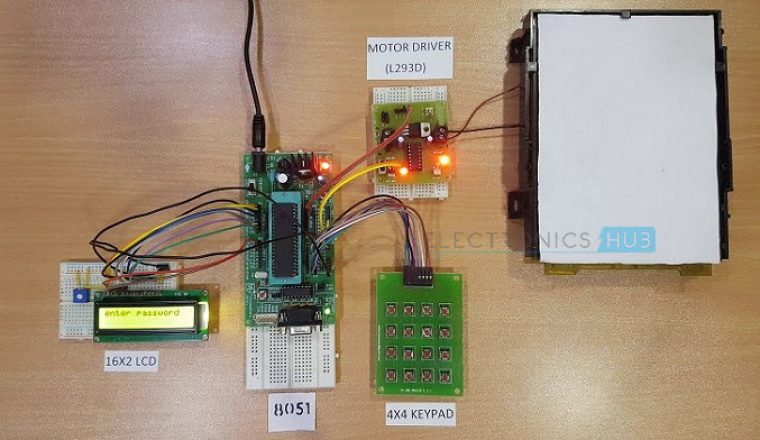
Password Based Door Lock System using 8051 Microcontroller
Here, we developed an electronic code lock system using 8051 microcontroller (a Password based Door Lock System using 8051 Microcontroller), which provides control to the actuating the load. It is a simple embedded system with input from the keyboard and the output being actuated accordingly.
This system demonstrates a Password based Door Lock System using 8051 Microcontroller, wherein once the correct code or password is entered, the door is opened and the concerned person is allowed access to the secured area. Again, if another person arrives, it will ask to enter the password. If the password is wrong, then door would remain closed, denying access to the person.
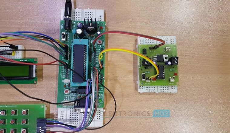
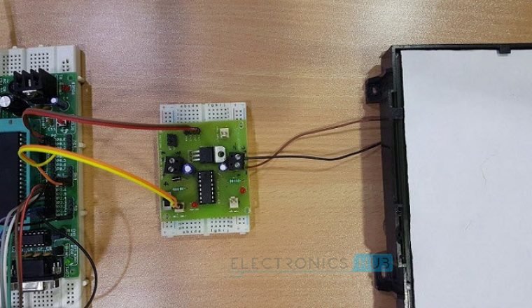
Construction and Output Video
Recommended Reading: Electronic Code Lock System using Single Transistor
Principle Behind the Circuit
The main component in the circuit is 8051 controller. In this project, a 4×4 Matrix Keypad is used to enter the password. The password which is entered is compared with the predefined password.
If the entered password is correct, then the system opens the door by rotating door motor and displays the status of door on LCD. If the password is wrong, then the door is remains closed and displays “PWD is wrong” on LCD.
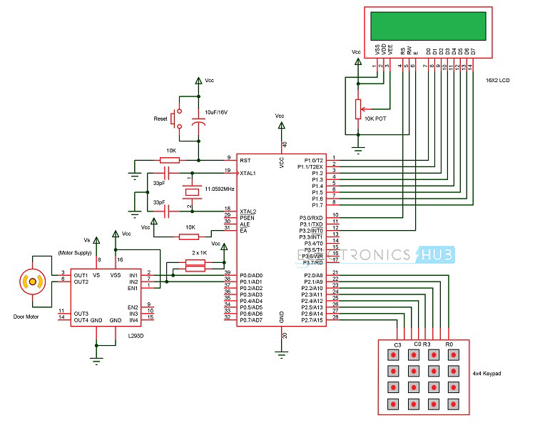
Circuit Diagram of Password Based Door Lock System
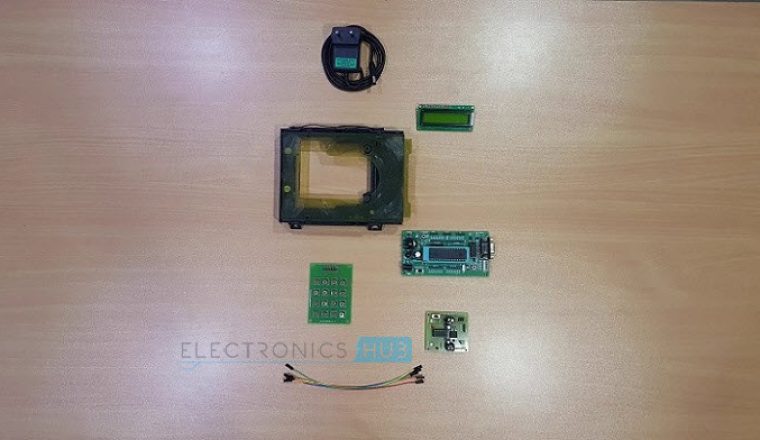
Components Required
Hardware Requirements
- 8051 Microcontroller
- 8051 Development Board
- 8051 Programmer
- 4×4 Matrix Keypad
- 16×2 LCD
- L293D Motor Driver Board
- DC Motor
- 10KΩ Potentiometer
- Connecting wires
- Power Supply
- If 8051 Development Board is not used, then the following components are needed.
- 11.0592 MHz Quartz Crystal
- 2 x 33pF Ceramic Capacitors
- 2 x 10 KΩ Resistor (1/4 Watt)
- 10 µF Capacitor (Polarized)
- Push Button
- 2 x 1 KΩ Resistors (for pull up)
Software Requirements
- Keil µVision IDE
- Willar Programmer
- Proteus (for circuit diagram and simulation)
How to Design Circuit of Password based Door Lock System?
Password based door lock system using 8051 microcontroller circuit design uses five major components – a Microcontroller, an L293D Motor Driver, a DC Motor, a 4×4 Matrix Keypad and a 16×2 LCD. Here, an AT89C52 Microcontroller is used and it is an 8-bit controller. This controller requires a supply voltage of +5V DC. In order to provide regulated 5V DC voltage to the controller we need to use 7805 power supply circuit. We can use 9V DC battery or 12V, 1A adaptor as a power source.
Reset Circuit Design: The reset pin of the microcontroller is kept active till the power supply is in the specified range and a minimum oscillation level is maintained. In other words to ensure the supply voltage does not falls below the threshold level of 1.2V and the reset pulse width is greater than 100ms (recommended for 89C52), we need to select the values of resistor and capacitor such that RC >=100ms. Hence, we selected a 10KΩ resistor and a 10µF electrolytic capacitor.
Oscillator Circuit Design: An 11.0592MHz crystal oscillator is used to provide external clock signal to the microcontroller. To ensure smooth operation, we need to connect two ceramic capacitors in the range of 30pF to 40pF. This crystal oscillator is connected between pin 18 and 19 of the microcontroller. Here, we used two 33pF capacitors.
Interfacing LCD, Keypad and Motor Driver: First, a 10KΩ Potentiometer is connected to the LCD Display’s Contrast Adjust Pin (Pin 3). RS, RW and E of LCD are connected to P3.0, GND and P3.2 pins respectively. The eight data lines of the LCD are connected to PORT1.
The four ROW pins of the Keypad are connected to P2.0 to P2.3 and the four COLUMN pins of the Keypad are connected to P2.4 to P2.7 pins respectively. The IN1 and IN2 of (1A and 2A) of the L293D Motor Driver are connected to PORT0 pins P0.0 and P0.1. Motor is connected between OUT1 and OUT2 (1Y and 2Y) pins of L293D.
Compilation of Microcontroller Code: Once the circuit is designed and drawn on a piece of paper, the next step is to write and compile the code. Here, we used the Keil µVision software to write the program in C language.
Prior to writing the code, general steps needs to be followed like creating a new project and selecting the target device or the required microcontroller. Once the code is written, we need to save it with .c extension and then add it to the source file group under the target folder. The code is then compiled by pressing F7 key.
Once the code is compiled, a hex file is created. In the next step, we use Proteus software to draw the circuit. The code is dumped into the microcontroller using an external programmer and Willar Software.
Recommend Reading: Password Based Circuit Breaker Project Circuit Diagram and Working.
Password Based Door Lock System Circuit Simulation Video
Before going to read the working of this circuit, Watch the following simulation video to get clear idea about how the above circuit works.
DOWNLOAD PROJECT CODE
Password Based Door Locking System Circuit Operation
Once the circuit is powered ON, microcontroller sends commands to the LCD to display “enter password” on LCD. Now we need to enter the password using the keypad. Once password is entered, it displays 5 stars on LCD to indicate that controller read password successfully.
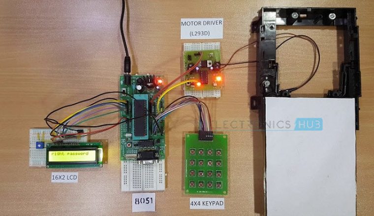
Now the controller compares the entered password with predefined password. If the password is matched, then the microcontroller makes P0.0 HIGH and P0.1 LOW, so the motor driver gets the input signals for forward motion of the motor.
As a result, the Door Motor rotates in forward direction to open the door. After a delay of 10seconds, the microcontroller makes P0.0 LOW and P0.1 HIGH, so the motor driver gets the input signals for reverse motion. As a result, the Door motor rotates in reverse direction to close the door.
If the password is not matched, then microcontroller maintains both P0.0 and P0.1 LOW. Hence, the door motor is stationary so that door remains closed.
NOTE: While giving the connections, make sure that there is no common connection between AC and DC supplies.
Password Based Door Lock System Algorithm
- Initially, declare the PORT1 to LCD data pins and control pins (RS and E) to P3.0 and P3.2. Also, declare PORT2 to keypad. Also use P0.0 and P0.1 for motor driver.
- Then, display the message “enter password” on LCD.
- Now read the five digit password from the user.
- Compare the entered password with the stored password.
- If password is correct, then make P0.0 pin HIGH and P0.1 pin LOW to open the door. During this time, display “Door opening” on LCD.
- After some time, make P0.0 pin LOW and P0.1 pin HIGH to close the door and after this display “Door closing” on LCD.
- If the password is wrong, then display “Wrong Password” on LCD.
- After some delay again ask to enter password.
[Also Read:Adjustable Timer With Relay Output]
Advantages of Password Based Door Lock System
- This project provides security
- Power consumption is less
- Used commonly available components
- Project is simple and easy
Applications of Password Based Door Lock System
- This simple circuit can be used at residential places to ensure better safety.
- It can be used at organizations to ensure authorized access to highly secured places.
- With a slight modification this Project can be used to control the switching of loads through password.
Limitations of Password Based Door Lock System
- It is a low range circuit, i.e. it is not possible to operate the circuit remotely.
- If you forget the password it is not possible to open the door.

123 Responses
i need code of this projact ” Password Based Door Lock System using 8051 Microcontroller:”
Please have a look at article, we have updated project code.
admin plZz can i have d project code…
i’m trying to replicate your project
please send code i am working on this one
the code in this article have some error in 12th n 13th line
so could u plz upload correct code n plz send dat code to my mail
i will be bery glad to have dat
AOA SIR CAN YOU SEND ME THE CODE OF THIS PROJECT?
The project coding which you given in this article has one error which I can’t able to resolve..
Please help me to overcome it..
The error is “str_lcd: has ANSI style prototype”…
what is the solution for it please mail it to my email id
Can i have the code please? We really need this for our project.. send it to my email. Thank you so much. I’ll appreciate it! ?
I HAVE MADE IT
SIR PLEASE SEND ME THE CODE OF THIS PROJECT?
Will you please reply here with the full code
I need this project with assembly language
hye….i need that code too…..can u share it with me???
Hi, can you share the code?
I need this project for practice.I shall be very thankful to you.
We have provided everything in article.
i need codes of this project in assembly (.asm) please..
Project code you can find in the article.
where it is ?we cant find it in the above Article so could you please post the code for the project ?
i need code of this projact ” Password Based Door Lock System using 8051 Microcontroller:”
Please check the article, we have uploaded project code.
cant find the code..its no where in the article…
Please have a look, it’s there after the circuit diagram.
please send me more projects
Yeah, we do more projects, keep following us, thanks for your support.
What is cost of this projects
It’s FREE. 🙂
pl were i want get the password based door lock systems use spare parts and pcb
This is a very good project for the security i need this project
Yeah you can try to make this project based on above article, all the best.
i like to have guideline on this project thanks
i need this project with assembly language &8051 microcontroller circuit diagram & apparatus required & report format please send to my email id
sureka17091993@gmail.com
Can i get more projects based on microcontroller….
Hey!
I need the code for the project “Password Based Door Lock System using 8051 Microcontroller” at the earliest. I would be really greatful to you if you could help me out with this!
We have updated project code long back, you may check it in the above article. Thank you.
How do you store the input password in a array variable and compare it?
plz send me the c prog file
Hi, I had a quick question regarding the project design to whether or not it will be able to communicate with the main controller such as the RFM73 transceiver or not. I tried emailing you at admin@electronicshub.org, but it says this email is invalid.
Email is not deliver to your id. Please email me the coding in C language.
Thanks.
Truthfully its awesome especially for the students like me.
Most energetic comment for us, we always love your support and cooperation. Thank you so much for your feedback.
Hey can u send me the code . I urgently need it.
suppose the password forget there is no option for operate the door lock system why..? i mean why cant be reset the password
I need the code for this project
I need the code for this project as a guideline for university project
can we change the length of password………….?????
I would like to receive the code, I have a code written and it compiles fine but there is a glitch that I am having that I seem to cannot find. This is a project sin school. Thank you
i need coding for project
i need coding beacuse i am ay initial stage of programing
plz snd program on thAT e.mail
hirfan311@gmail.com
i need code of this projact ” Password Based Door Lock System using 8051 Microcontroller:” in Aurdino formatt…if any one have plz snd me in my email plz…..email…..zubairkhoso21@gmail.com
i need code of this projact ” Password Based Door Lock System using 8051 Microcontroller:”..arduino format base…any one have then plz email me …..zubairkhoso21@gmail.com
This is really helpful.. Can you give us the code for us to try.
Thank you..
I am interested in this project work
That’s a awesome project, many people are showing interest to do this project. All the best.
can u give me project source code in arranged way(in one file)
Need the project code can u plz send me to my email the above code shows corrupted. Thank u
i need this project code to learn myself as i wan to specialized in this kind of science , so i wan to check if there was any something wrong with my assembly code
Project code is uploaded..Please check in the article
Hey can u send me the code . I urgently need it. This site can’t reached error is coming again and again.
I need this project because it is my final year project topic.
Please I need this project, but I need the code that can help me change the stored password.
And please admin help me drop some comments that explains the codes so I can be able to explain during defecne
i am interested to do this project but can anyone tell me instead of door motor what else we can use to show that the door is locked or not??
I need the code for my graduation project
sir can i hace hex file
Please give full code to aid for my course project
sir, please tell me what is the project code means………
please can you give me the PCB layout and block diagram of this project.
This is a very good project for security… i want to made this ..
Plese tell me requirements for this project.
And send me code for microcontroller..
this method for yhis project is much difficult ……………….
Hey I need the code for the project “Password Based Door Lock System using 8051 Microcontroller” as early as possible. it would great if u do the needful.
I need the code for this project as early as possible. it would be great if u do the needful
Actually I want to do a mini project on this topic because I need it…plz help me and send me code… Thank you!
I need code for this project plz …m making the same.project for my mini project in college…plz…rpy to me asap…I need the code ..tysm
Useful
I am making the same project as I have taken this project as my topic for mini project so con you please provide the programs.
Can you please provide me with the assembly level code. I am learning how to use the hardware and I saw this video on youtube and it seemed like an interesting project and one which I can learn from. I would be extremely obliged if you could provide me with the assembly level code.
I am making the same projectas I have taken this project as my topic for mini project so con you please provide the programs.
send me code plz..
i m making this project please give me the code
I need code for ths project as i am doing it as mini project in my colg so plz send me the code using 8051 microcontroller” if it s in arduino format base thn it would be of great help ty
i need this project code because i wan to implement my last year graduation project
plz give me the code of this project
Hi, we have already uploaded the project code please check it
hi i am sandhya .I need project code of this project for my last year project submission. Can u give me project code of”password door lock system using 8085 ‘in assembly language?
I need a project code in c language for mini project…pls provide code….
i need the code of door lock password project… this is the first time am doing dis… first am going to try the same project…
We have uploaded the code…Go through the article completely..we have provided link below simulation video
The project code uploaded by you is not opening after the download please snd us a original code to replicate your project.
Please try to install keil software to open these files
my circuit is ready but ,
program not available ice 8051
plz send program on that mail
mahaveerbora968@gmail.com
Code is uploaded in the article.Please download the code from article.
m interested in dng the project.. can u plz send me the code
Plz send the code..it’s my 1st project..
Download code from the article
Can u pls send me the program in c language my email I’d is shanunaik0806@gmail.com
Download code from the post..It is written in C
sir tell me the specification of dc motor that used in password door lock system.
Why that relay is required in the project we can rotate the stepper motor without relay also?
In real time we may use AC motor..Relay is used to provide isolation here.
Can I get this ic at89c59 with this program burnt on it for password protection door locking system?
Can you send me .SCH file at myeole1995@gmail.com
i need codes of this project in assembly (.asm) please..
I want assemblylanguage code for this project.And I m not able to find asm file only C file is there n no asm file..Can u pls mail it to me??or pls re-post the link here again.
i am trying to make this project’
but iam facing the problem while creating hex file
can you provide me hex file or help me in creating it with keil
i’ll be very thankfull to u
please admin. how do i combine the codes in the compiler. this is my final year project
Please be clear with your question..
where is the code ? i can’t see it anywhere in the article if it’s really in the article then please upload the link.
Help ?
Please Name the Simulator Software Use in This Video.
I also need of code password based door lock system
Which Software u used to implements the parts .. E:g Multisim ,
kindly answer bcs i cant find microcontroller at89c51 in multisim. Thank u
how do we connect the preset to LCD?
please help me with the connections of preset with LCD
can i get programming of it ???? plzzz
where i can find the hex file or the programe to commond the microcontroller????
I am working on this project based on this article but i have a problem with hardware. In Proteus project works good but when implement on hardware its not working … please guide me admin.
I thinkthis is really interesting to doo i like it to be implemented
PLEASE I NEED THE CODE FOR MICROCONTROLLER BASED LOCK USING COLOUR SECURITY CODE IF ANY
Programme for. 8051
sir i am enggineering student ……i have been given this project (PASSWORD BASED LOCK DOOR SYSTEM) send me the code of this project i will be very grateful to you
my email address: aftab40000@gmail.com
Please go through this course for code and complete information
How much voltage require for dc motor here
i have to do the same project using tiva launchpad. can i use the same code for tiva???
Hiiii
What is the cost of this project??
if we forgot the the password means what to do..??
if password is incorrect how many times we have to enter the pin