

Password Based Circuit Breaker is a simple project that helps in controlling the electrical lines with the help of a password.
Nowadays, electrical accidents to the line man are increasing, while repairing the electrical lines due to the lack of communication between the electrical substation and maintenance staff. This project gives a solution to this problem to ensure line man safety. In this proposed system, the control (ON/OFF) of the electrical lines lies with line man. This project is arranged in such a way that maintenance staff or line man has to enter the password to ON/OFF the electrical line.
Now, if there is any fault in electrical line, then the line man will switch off the power supply to the line by entering password and comfortably repair the electrical line, and after coming to the substation line man switch on the supply to the particular line by entering the password. Separate passwords are assigned for each electrical lines.
Before going to know about this circuit, also read the interesting post: Password based door locking system.
Password Based Circuit Breaker
Construction and Output Video
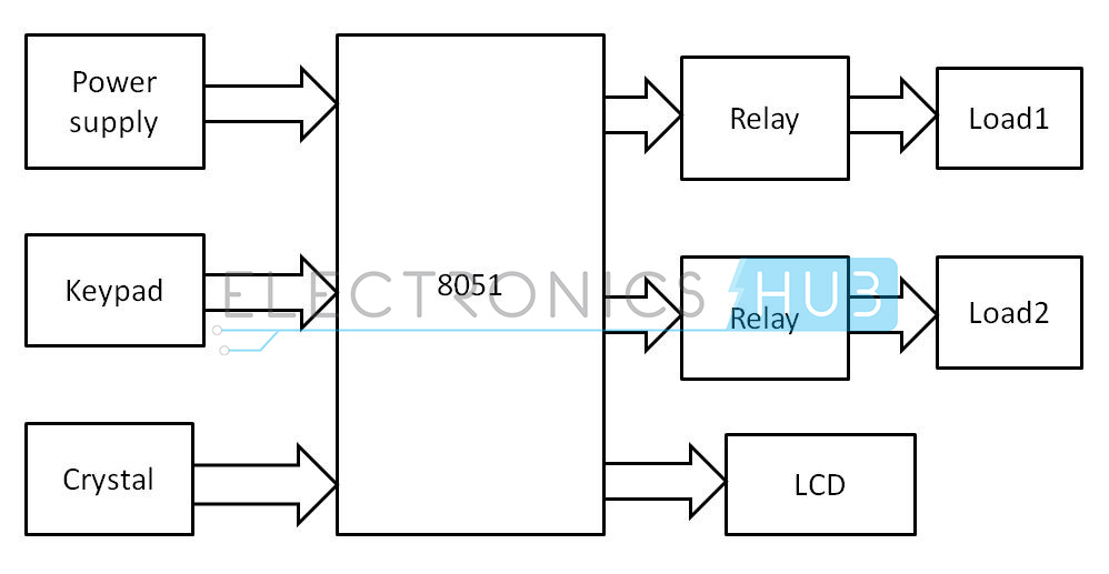
Password Based Circuit Breaker Block Diagram
Principle of Operation
The main component in the circuit is 8051 microcontroller. In this project 4×4 keypad is used to enter the password. The password which is entered is compared with the predefined password. If entered password is correct, then the corresponding electrical line is turned ON or OFF. In this project, a separate password is provided to each electrical line. Activation and deactivation of the line (circuit breaker) is indicated by the load (Light Bulbs).
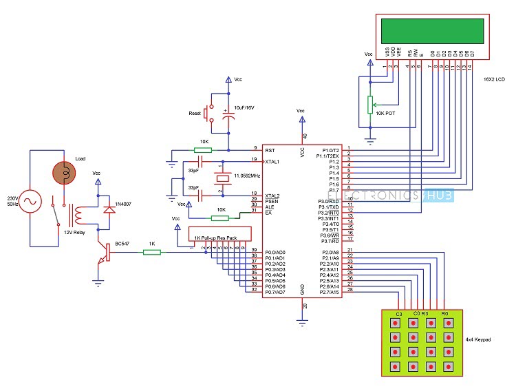
Circuit Diagram of Password based Circuit Breaker
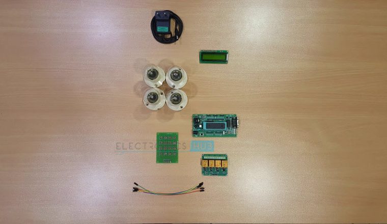
Components Required
- 8051 Microcontroller (AT89C52)
- 8051 Development Board
- 8051 Programming Board (Programmer)
- 4 x 4 Matrix Keypad
- 4 – Channel Relay Module
- 16 x 2 LCD Display
- 10KΩ Potentiometer
- 4 Loads (Light Bulbs)
- Power Supply
- Connecting Wires
- If 8051 Development Board is not used, then you need
- 0592 MHz Crystal
- 2 x 33pF Capacitor
- 2 x 10KΩ Resistors (1/4 Watt)
- Push Button
- 10µF Capacitor (Electrolytic)
- 1KΩ x 8 Pull – up Resistor Pack
- If Relay Module is not used, then you need (components mentioned for one load)
- 5V or 12V Relay
- 1KΩ Resistor (1/4 Watt)
- BC547 NPN Transistor
- 1N4007 PN Junction Diode
Password based Circuit Breaker Circuit Design:
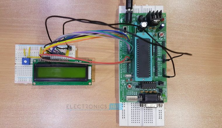
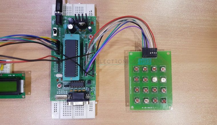
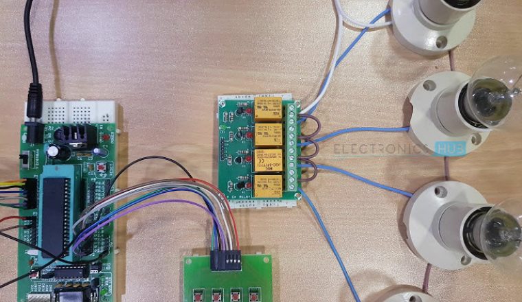
The above circuit consists of 8051 series controller (AT89C52), 4×4 Matrix Keypad, 16 x 2 LCD Display, 4 – Channel Relay Module and Four Loads. LCD data pins are connected to PORT1 and control pins RS, RW and EN pins are connected to P3.0, GND and P3.1 respectively. Here, the LCD is used to display the information related to the load.
Keypad is connected to PORT2 of the microcontroller. The four Row Pins of the Keypad are connected to P2.0 to P2.3 and the four Column Pins are connected to P2.4 to P2.7. Using this keypad, we need to enter the password.
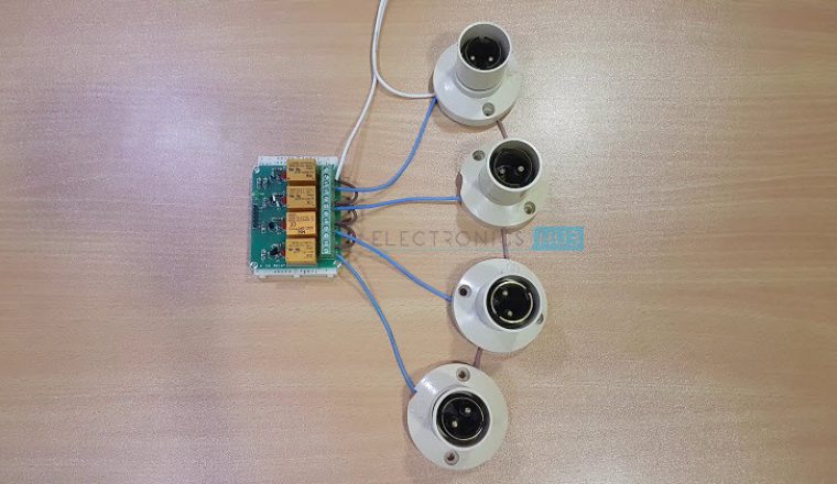
Four Lamps (acting as Electrical Lines) are connected to P0.0 to P0.3 through the 4 – Channel Relay Module. These are used to indicate circuit breaker state (Light ON – Line Active and Light OFF – Line Not Active).
If you are not using the Relay Module, then you need to use 4 BC547 NPN Transistors (along with its current limiting base Resistor) in order to drive the relays.
WARNING: Be extremely careful when wiring the AC load to the Relay and mains supply.
Algorithm
- Initially declare the PORT1 to LCD data pins and its control pins RS and E to P3.0 and P3.2 and P3.7 respectively. Also declare PORT2 to keypad and use P0.0, P0.1, P0.2 and P0.3 to loads.
- Initially display “enter password” on LCD.
- Now read the five digit password from the user.
- Compare the entered password with stored password.
- If the password matches, correct then ON or OFF the particular load and display line or load status on LCD.
- If the password is wrong, then display “wrong password” on the LCD.
- After some delay, again ask to enter password.
Simulation Video
How to Operate the Password based Circuit Breaker Project?
- Write the program to the Password based Circuit Breaker in Keil software and create .hex file.
- Burn program to the controller with help of 8051 Programming Board and Willar Software.
- Now give the connections as per the circuit diagram.
- While giving the connections, make sure that there is no common connection between AC and DC supplies
- Use 5V power supply circuit to provide regulated 5V DC to the controller.
- Switch on the both AC and DC supplies.
- Now relay output pins gets 230V. So, do not touch the load connected pins.
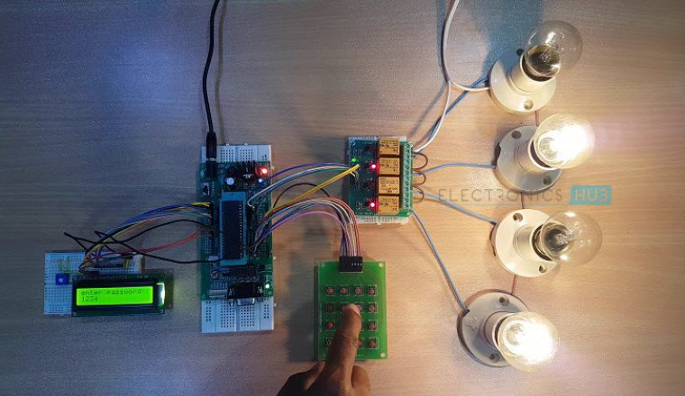
- LCD displays “enter password”.
- Enter the password with help of keypad.
- Now, if the password is correct, then circuit breaker changes its state (i.e. if it is already ON, now it becomes OFF and if it is already OFF, now it becomes ON) and displays line (or load) status on LCD.
- If the password is wrong, then the LCD displays “wrong password”.
- After some time, the microcontroller asks to enter password by displaying “enter password”.
Advantages
- Avoids electrical accidents to line man
- Project is simple and easy
- Uses commonly available components
Applications
- Used in electrical substations to ensure line man safety
- This system is used in buildings and houses
- Used in hotels and shopping malls to save the power.
- Can also be used as Password based electrical appliance control or Password based Load Control system.
132 Responses
sir plz send me all the details about this
I need it in June
Dear sir,
I want to do this project, but I want code of Password Based Circuit Breaker .kindly send to my Email
A relay is not the same as a circuit-breaker… just sayin’
You are right. A relay is not a Circuit Breaker.
please send the full project
I need an programming for password circuit breaker
Hi,
Did you got the final report or proposal of this Project
I want to do this project, but I want code of Password Based Circuit Breaker .kindly send to my Email
i need the code for this project
I am a B-TECH student please i will need the code to make the same project for my class project.
i realy impressed………wooooosm
Why you need this project code?
to make the semester project.
Are you trying to make the same project or different one?
i am trying the same project.
Give us more details about your project.
i am trying the same project and i want to install the system in my home.
ANS1: i want to make this project to save the lives of people from short circuit as well as save electricity. so that the villager areas may use. Ans 2 some kind of advance Ans 3 to give advantage of poor which can not have electricity in his home in a low price
sir plz send me this project coding.
I want Password based circuit breaker code.
I WANT FULL DETAILS ABOUT THIS PROJECT AT THE SIMPLE LANGUAGE
I would like to have this kind of project. Same project please send me or give the program of this project. thanks!
Project Code is uploaded..Please go through the article
I would like to have this kind of project so please send me the code to make this possible thanks!
Project code is uploaded..Please go through the article
I would like to have this project, please send me the codes in programming it. thanks!