One Transistor Electronic Code Lock System Circuit uses minimal components to deliver maximum security. It combines simple design with new technology. Ideal for keeping personal areas safe, this system shows that just one transistor can create a dependable security method. It’s an affordable and effective way to protect privacy and security in many places.
This article describes one transistor code lock circuit which is a key coded door lock system. Earlier, we have already seen how a password based door lock system works using 8051 microcontroller. For that circuit, we require programming. But, here interesting thing about this circuit is that it can be done without any programming. This circuit is simple and made up of simple transistor and buttons.
One Transistor Electronic Code Lock System Circuit Principle:
The main principle of this circuit is that the door lock opens only when the buttons in series are pressed at a time. If any button which is in parallel is pressed door is locked. When all these buttons are pressed transistor switches the relay and the door is opened. In real time these buttons can be arranged in an order to open the door.
One Transistor Electronic Code Lock System Circuit Diagram:
Circuit Components:
- Transformer.
- Bridge rectifier.
- Resistor.
- Capacitor.
- Buttons.
- Diode.
- Transistor.
- Relay.
- Motor
- Ac source.
Simple Transistor Code Lock Circuit Simulation Video:
One Transistor Electronic Code Lock System Circuit Design:
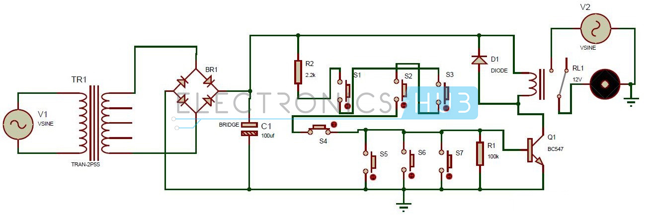
The circuit consists of a stepdown transformer whose input is AC supply of 230V and 50HZ. In the stepdown transformer, number of windings in the primary coil is less than the number of windings in the secondary coil.
It is connected to the bridge rectifier. The bridge rectifier rectifies the full wave coming from the transformer .It has 4 pins in which two pins are connected to the transformer. In the other two pins, one is connected to ground and the other pin is connected to the resistor and capacitor. Capacitor other end is grounded. From the resistor, four buttons S1, S2, S3 and S4 are connected in series. Now from the next button S5, they are connected in parallel. Thus S5, S6, S7 are connected in parallel.
A resistor of 100k is connected in parallel to the buttons. Base of the transistor is connected to the buttons in parallel. Emitter pin of the transistor is connected to the ground. Collector pin is connected to the 1N4007 diode, relay. Other end of the diode is connected to the one end of the relay. Here diode is used for protecting transistor, as relay produces back emf. Relay has five pins. One pin is connected to the positive terminal of the diode. Other pin is connected to the ground. Thus relay output is connected to the motor through its AC source.
The relay used here is a magnetic relay. It has five pins i.e. NC, NO, COM, A, B. A, B are the inputs of the coil .When no voltage is applied to these pins, COM pin is connected to the normally closed pin i.e. NC pin. When a DC voltage is applied to A, B pins of the relay, the COM pin is connected to the normally open pin i.e. NO pin of the relay.
Simple Transistor Electronic Code Lock System Project Output Video:
How One Transistor Electronic Code Lock System Circuit Works?
- Initially, apply the input voltage of 230V and 50 HZ to the transformer.
- Thus, step down transformer reduces this voltage to 6V.
- This reduced AC voltage is applied to the bridge rectifier. This outputs a pulsating DC.
- The output voltage is applied to the buttons through a resistor of 2.2K ohms.
- Now initially press the switch S1 and then press switch S3.
- Now press the switches S2 and S4.
- Now current flows through these switches to the transistor base as the parallel buttons are opened.
- The relay starts switching and supply is connected to the motor.
- Now, you can see the motor rotating, indicating that its door lock is open.
Electronic Code Lock System Circuit Advantages and Applications:
- This circuit is very simple, reliable and low cost.
- We can use it in security applications.
- We can also use it in door lock systems to open the door.
Limitations of this Circuit:
- If the user forgets the password i.e. the order of the buttons to be pressed it is difficult to open the lock.

20 Responses
what range of bridge rectifier and transformer?
which diode we have to use?
i want full details of this paper plz reply quickly
1N4007 diode is used..
stepdown transformer 50hz 230v is required
Then what are the use of S5,S6,S7 and 100ohm Resistance…??
its no matter the sequence,, if we press all the switches which are in series,, then the circuit will be turned on…
if u don’t know, don’t explain wrong concept.. Diode is used parallel with relay in reverse polarity in order to avoid high reverse flow of voltage when diode switched off..
relays having a bad property of generating high voltage of 4 times the voltage we applied. when they turned off, that voltage will defiantly damage the remaining components .. that is the actual reason we use a diode.
this project is vrey intresting. i need complete documentation of this project.
send to my email immediately
i like this project and i had decided to do this project and i want the details of this project
All the necessary details were provided in the article ..Please go through it
What is the values of the diodes and transformer. The above video is not useful at all.
Transformer used is 9v transformer..1n4007 diode is used
what is the bridge rectifier used??
what is the bridge rectifier used in this circuit??plz give the answer fast…
Can you please explain the use of the transistor in this project? Plz reply ASAP….
will you send the full details about this project to my mail id please? because i have planned to do this project as main. but i don’t know all the appropriate values of components.
I planned to work at this but
How to connect the relay to the bread board ?
Plz reply
can you please tell the values of all components and what is the use of Bridge rectifier and value of it as well. Thank yoy
What Tipe Of Switches Are Used
I want the simulation process of one transistor electronic code lock system
how to design the resistor 2.2k and capacitor 100uf?
For what use should we using this s5,s6,s7 switches her???
??
because if we press the switches in parallel the circuit will break and the current will not move forward so th e door will be not unlocked.