In this project, we will learn how to write data to MIFARE 1K RFID Card using RC522 RFID Reader / Writer Module. This is useful if you want to store custom data on the tag like student information or employee details.
We will use Arduino as the host controller to interface with RC522 RFID Module and write data to RFID card. I already made a tutorial on how to interface RC522 RFID Module with Arduino. Check out that tutorial before proceeding further as there are some basics related to RFID Communication, MFRC522 IC, RC522 RFID Module and more.
A Brief Look at Memory Map of MIFARE 1K Tag
If you upload the ‘DumpInfo’ example and open the serial monitor, Arduino will print all the contents of the MIFARE 1K RFID Tag on the serial monitor after scanning it properly.
It is very important to understand the memory layout of the RFID Tag as we will know what is the significance of each memory location, what memory locations are reserved and what locations are free to use for storing user data.
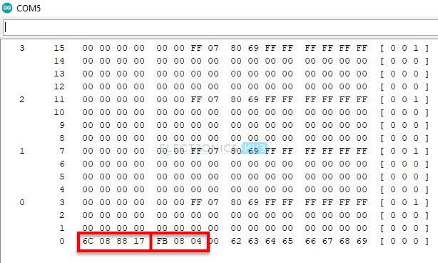
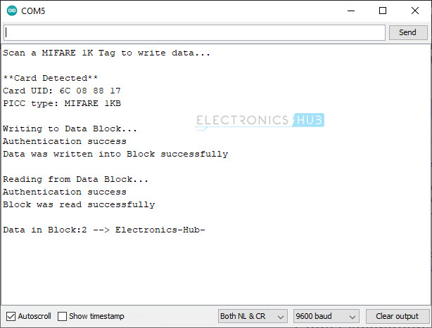
The following image is a screen shot of the serial monitor output of ‘DumpInfo’ example. Let us now analyze this.
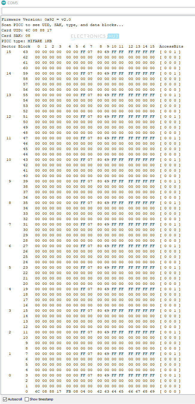
Analyzing Serial Monitor Output
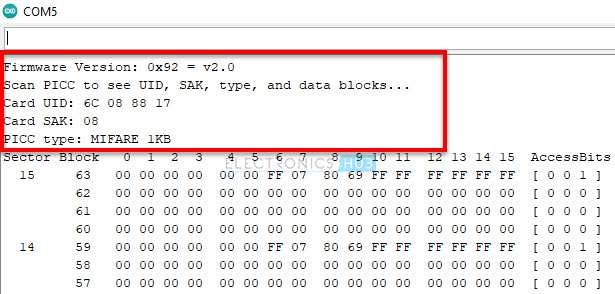
The first line shows the firmware version of the MFRC522 IC. In this case, the result is 0x92. Here, ‘9’ stands for MFRC522 IC and ‘2’ stands for software version 2.0. After scanning the RFID Card, we get the UID, SAK and Type of RFID tag.
In this case, the UID is ‘6C 08 88 17’, SAK is ‘08’ and the type of card is MIFARE 1K.
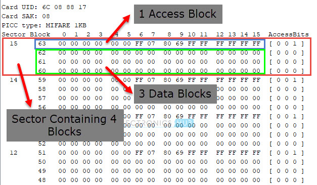
Next, you can see the actual memory dump of the MIFARE 1K Tag. A typical MIFARE 1K RFID tag has 1K Byte of memory organized into 16 Sectors (Sector 0 to Sector 15). Each Sector consists of 4 Blocks.
Understanding memory Map of MIFARE 1K Tag
For example, Sector 0 has Blocks 0, 1, 2 and 3. Sector 1 has Blocks 4, 5, 6 and 7 and so on and finally Sector 15 has Blocks 60, 61, 62 and 63. Each Block can store 16 Bytes of data.
NOTE: This numbering is just to understand the memory layout.
So, 16 Sectors * 4 Blocks * 16 Bytes = 1024 Bytes = 1K
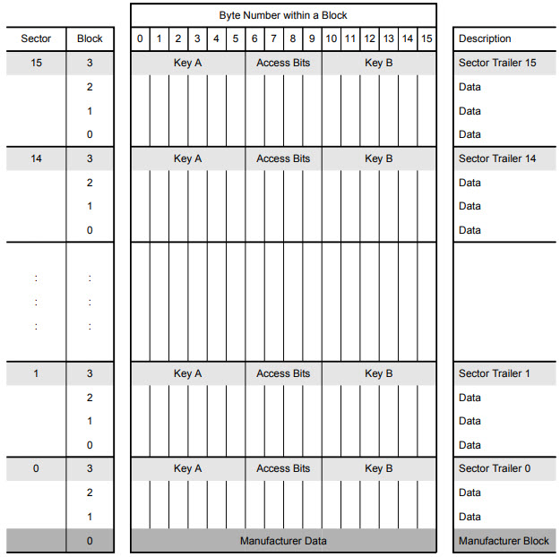
Block 0 of Sector 0 is reserved for storing Manufacturer Data. Usually, this Block contains 4 Byte UID (Unique ID) in case of MIFARE 1K Tags (and also MIFARE 4K, MIFARE Mini tags from NXP). Advanced Tags like MIFARE Plus, MIFARE Ultralight, MIFARE DESFire consists of a 7 Byte UID.
Each Sector consists of three Data Blocks, which can be used for storing user data. The last Block of each Sector i.e., Block 3 in case of Sector 0, Block 7 in case of Sector 1 and so on is known as Sector Trailer.
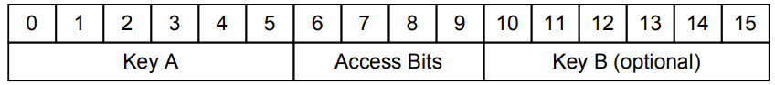
As there are 16 Sectors, there are 16 Sector Trailers. Each Sector Trailer consists of the following information:
- A mandatory 6 Byte Key A.
- 4 Bytes for Access Bits.
- Optional 6 Byte Key B (if not used, data can be stored).
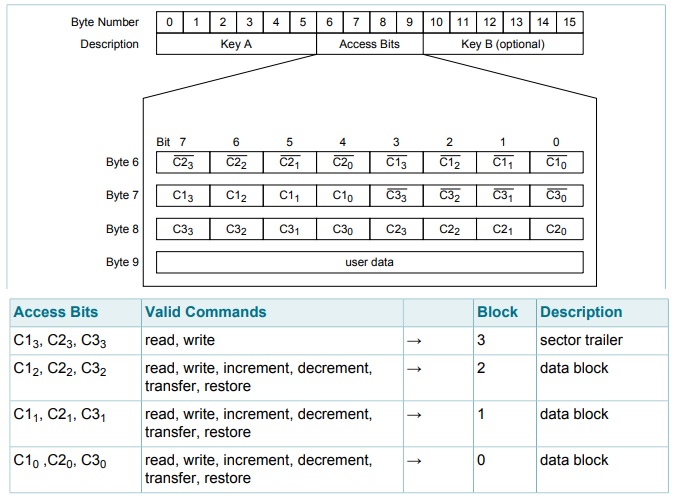
NOTE: Byte 9 in the ‘Access Bits’ region is available for user data.
NOTE: All sectors have three data blocks and one sector trailer except sector 0. It has one block (Block 0) reserved for Manufacturer Data. So, Sector 0 has two data blocks and one sector trailer.
The Access Bits in the Sector Trailer determine the access conditions for all the blocks of a Sector. 3-bits are needed for specifying access conditions for the three data blocks and the sector trailer. The access condition includes Read, Write, Increment, Decrement, Transfer and Restore.
With all this information, we can conclude that, you can store 47 Bytes of Data in a MIFARE 1K RFID Data. Let us now see how to Write Data to RFID Tag using Arduino and RC522 RFID Module.
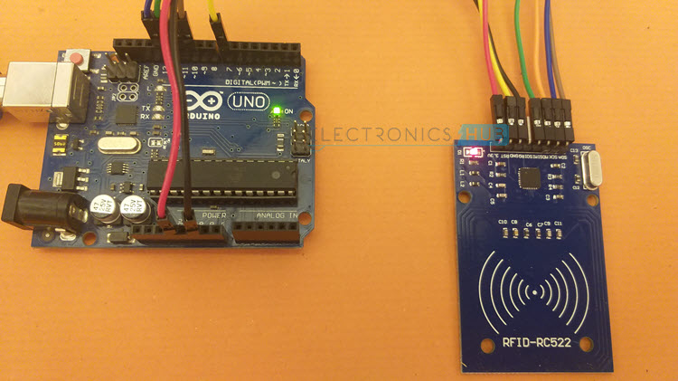
Interfacing RC522 with Arduino
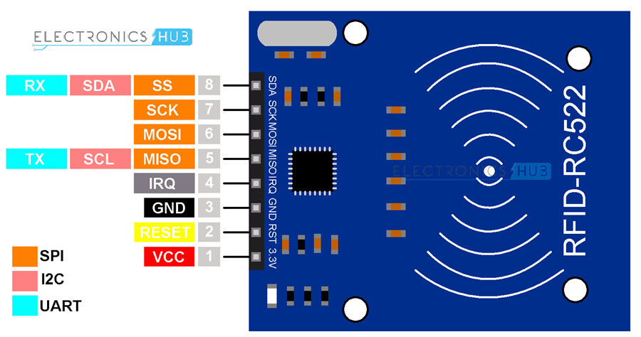
Even though MFRC522 IC supports three types of Serial Communication; UART, SPI and I2C, the SPI Interface is the fastest and most common. The following image shows the pinout of RC522 RFID Module.
For reliable communication between Arduino and RC522, let us use the Hardware SPI Pins. The following table shows the connections between Arduino and RC522 Module.
|
RC522 RFID Module |
Arduino UNO |
|
VCC |
3.3V |
| RST |
7 |
|
GND |
GND |
| IRQ |
—- |
|
MISO |
12 |
| MOSI |
11 |
|
SCK |
13 |
| SS |
10 |
Components Required
- Arduino UNO
- RC522 RFID Reader / Writer Module
- MIFARE 1K RFID Tag
- Connecting Wires
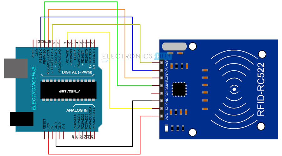
Circuit Diagram
The following image shows the connections between Arduino and RC522 RFID Module.
Write Data to RFID Card
I wrote a simple program in which I write data to 1 Block (Block 2) and fill it completely. This means, the length of the data should be 16 Bytes.
Code
The Arduino code for writing data in to MIFARE 1K RFID Tag is given below. I commented the code so that you can understand it easily.
Conclusion
A simple demonstration on how to Write Data to RFID card using RC522 RFID Reader / Write Module and Arduino UNO. You learned the memory layout of MIFARE Classic 1K RFID Tags, memory locations feasible to write data and also write some random text to an RFID Card.

12 Responses
Hi Ravi, thanks for the useful and informative article. I tried using the programme as above. The data was able to be written into the block successfully. However, when reading from datablock it states as “authentication fail for read: Timeout in communication”. Any idea as to why that is? Thanks again!
You are probably taking out the RFID Tag / Card too soon before the reader could communicate with it.
Try not to remove the RFID Tag until the reader could read from it.
I’m getting a timeout in communication during reading. I tried to implement the code into my own code so what could I have done wrong?
When I run this code with the writing part commented out, it wil only read 1 time and then get stuck in the “if ( ! mfrc522.PICC_IsNewCardPresent())” statement. How can I fix this?
Hi Ravi, Thx you for the article, I loved it and also helped me out on a personal project I’m doing. I have a problem with your code, I noticed that after the “mfrc522.PCD_Authenticate” in the Write and Read methods the arduino let finish the program, but then cannot let me write on any other card and everytime I need to reset the arduino. I tried to comment that line and indeed in this way the program go forward and can do more cards, but without it dosen’t really write anything on the card and just give an error message for each card. I would like to ask if is possible to write on a card and without having to reset the arduino I could write on a second card. Do you think is possible? Thank you in advance
Hi, this is very helpful. For instance, I would like to read/write onto 2 or more Blocks. How can I modify the code above to achieve that?
Hi. It said “initializer-string for array of chars is too long [-fpermissive]” for line 20. How to fix this?
Did you manage to fix this because l’m facing same problem?
Hi, Ravi..
I accidentally write to block 0 or block 3. Now my tag isn’t working. Is there anything I can do to reset the tag or something to fix this tag?
Thanks.
Chanuka : you can try “fixBrickedUID” from the examples in the used library Github /miguelbalboa/rfid
Also from Arduino IDE you can install and use it.
Is their anything special that needs to be configured in order to use I2C for RC522?
Thanks, this helped me starting to understand it much more!
Is it possible to read after writing, coming back later and the read what’s on the card?
DumpInfo only gives the HEX value’s so not really readable.