In this tutorial, we will learn about Silicon Controlled Rectifier (SCR). We will learn its symbol, structure, working, Turn ON and Turn OFF methods and some applications.
The Silicon Controlled Rectifier (SCR) is the most important and mostly used member of the thyristor family. SCR can be used for different applications like rectification, regulation of power and inversion, etc. Like a diode, SCR is a unidirectional device that allows the current in one direction and opposes in another direction.
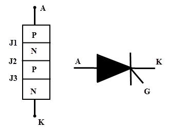
SCR is a three terminal device; anode, cathode and gate as shown in figure. SCR has built in feature to turn ON or OFF and its switching is controlled by biasing conditions and gate input terminal.
This results in varying the average power delivered at the load , by varying the ON periods of the SCR. It can handle several thousands of voltages and currents. SCR symbol and its terminals are shown in figure.
Construction of Silicon Controlled Rectifier
The SCR is a four layer and three terminal device. The SCR consists of four alternating P and N layers, forming three junctions: J1, J2, and J3. These junctions are either alloyed or diffused based on the type of construction.
The outer layers (P and N-layers) are heavily doped whereas middle P and N-layers are lightly doped. The gate terminal is taken at the middle P-layer, anode is from outer P- layer and cathode is from N- layer terminals. The SCR is made of silicon because compared to germanium leakage current in silicon is very small.
To manufacture the SCR, three types of constructions are used, namely the planar type, Mesa type and Press pack type. For low power SCRs, planar construction is used where all the junctions in an SCR are diffused. In mesa-type construction, junction J2 is formed using the diffusion method, while the outer layers are alloyed to it.
This construction is mainly used for high power Silicon Controlled Rectifiers. To provide high mechanical strength, the SCR is braced with plates made up of either molybdenum or tungsten. And one of these plates is soldered to a copper stud which is further threaded to connect the heat sink.
Working or Modes of Operation of SCR
Depending on the biasing given to the SCR, the operation of SCR is divided into three modes. They are
- Forward blocking Mode
- Forward Conduction Mode and
- Reverse Blocking Mode
Forward Blocking Mode
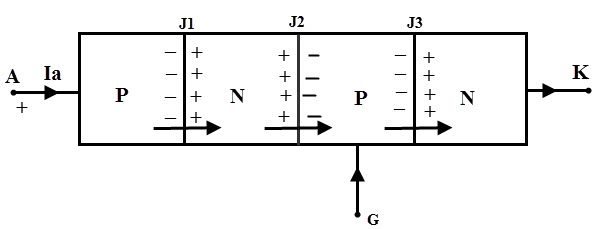
In this mode of operation, the Silicon Controlled Rectifier is connected such that the anode terminal is made positive with respect to cathode while the gate terminal kept open. In this state junctions J1 and J3 are forward biased and the junction J2 reverse biased.
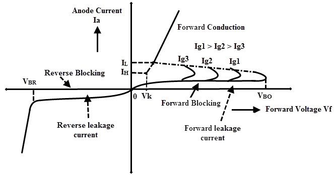
Due to this, a small leakage current flows through the SCR. However, the SCR maintains very high resistance to current flow until the voltage applied across it exceeds its breakover voltage. Therefore, the SCR acts as a open switch in this mode by blocking forward current flowing through the SCR as shown in the VI characteristics curve of the SCR.
Forward Conduction Mode
In this mode, the SCR (or thyristor) transitions from the blocking state to the conducting mode. It can be done in two ways as either by applying positive pulse to gate terminal or by increasing the forward voltage (or voltage across the anode and cathode) beyond the break over voltage of the SCR.
Once any one of these methods is applied, the avalanche breakdown occurs at junction J2. Therefore the SCR turns into conduction mode and acts as a closed switch thereby current starts flowing through it.
Note that in the VI characteristic figure, if the gate current value is high, the minimum will be the time to come in conduction mode as Ig3 > Ig2 > Ig1. In this mode, maximum current flows through the SCR and its value depends on the load resistance or impedance.
It is also noted that if gate current is increasing, the voltage required to turn ON the SCR is less if gate biasing is preferred. The current at which the SCR switches from blocking mode into conduction mode is known as the latching current (IL).
And also when the forward current reaches to level at which the SCR returns to blocking state is called as holding current (IH). At this holding current level, depletion region starts to develop around junction J2. Hence the holding current is slightly less than the latching current.
Reverse Blocking Mode
In this mode of operation, cathode is made positive with respect to anode. Then the junctions J1 and J3 are reverse biased and J2 is forward biased. This reverse voltage drives the SCR into reverse blocking region results to flow a small leakage current through it and acts as an open switch as shown in figure.
So, the device exhibits high impedance in this mode as long as the applied voltage remains below the reverse breakdown voltage VBR of the SCR. If the reverse applied voltage is increased beyond the VBR, then avalanche breakdown occurs at junctions J1 and J3 which results to increase reverse current flow through the SCR.
This reverse current causes more losses in the SCR and even to increase the heat of it. So there will be a considerable damage to the SCR when the reverse voltage applied more than VBR.
Two Transistor Analogy of SCR
The two transistor analogy or two transistor model of SCR expresses the easiest way to understand the working of SCR by visualizing it as a combination of two transistors as shown in figure. The collector of each transistor is connected to the base of the other transistor.
Assume that load resistance is connected between the anode and cathode terminals and a small voltage is applied at the gate and cathode terminals. When there is no gate voltage, the transistor 2 is in cut-off mode due to zero base current. Therefore, no current flows through the collector and hence the base of transistor T1. Hence, both transistors are open circuited and thereby no current flows through the load.
When a particular voltage is applied between the gate and cathode, a small base current flows through the base of the transistor 2 and thereby collector current will increase. And hence the base current at the transistor T1 drives the transistor into saturation mode and thus load current will flow from anode to cathode.
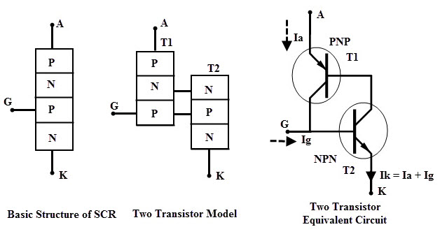
From the above figure the base current of transistor T2 becomes the collector current of transistor T1 and vice-versa.
Hence
Ib2 = Ic1 and Ic2 = Ib1
Also current through the cathode terminal, Ik = Ig + Ia ……(1)
For a transistor,
Ib1 = Ie1 – Ic1 ……(2)
and Ic1 = α1Ie1 + Ico1……(3)
Where Ico1 is the leakage current.
Substituting equation 3 in equation 2 we get
Ib1 = Ie1 (1 – α1) – Ico1 …….(4)
From the figure anode current is the emitter current of transistor T1,
Ia = Ie1
Then Ib1 = Ia (1 – α1) – Ico1
And also for transistor T2
Ic2 = α2Ie2 + Ico2
But Ik = Ie2
Therefore Ic2 = α2Ik + Ico2
Ic2 = α2 (Ig + Ia) + Ico2 …..(5)
But Ib1 = Ic2 …..(6)
Substituting the equations 4 and 5 in equation 6 we get
Ia (1 – α1) – Ico1 = α2 (Ig + Ia) + Ico2
Ia = [α2 Ig + Ico1 + Ico2] / [1- (α1 + α2)]
By assuming the leakage currents are negligible in both transistors we get
Ia = [α2 Ig] / [1- (α1 + α2)]
where α1 and α2 are the respective gains of the two transistors.
SCR Turn ON Methods
From the above equation, if (α1 + α2) is equal to one then Ia becomes infinite. That means anode current suddenly rises to a high value and latches into conduction mode from non-conductive state. This is called regenerative action of SCR. So for triggering of SCR the gate current value (α1 + α2) must approach to unity. From the obtained equation the conditions to turn the SCR into turn ON are
1. The leakage current through the SCR will increase when the temperature of the device is very high. This turns the SCR into conduction.
2. When the current flowing through the device is extremely small then α1 and α2 are very small. The conditions for break over voltage are the larger values of electron multiplication factor Mn and hole multiplication factor Mp near the junction J2. Therefore the by increasing the voltage across the device to break over voltage VBO causes the junction J2 breakdown and thereby the SCR is turned ON.
3. And also by increasing α1 and α2 break over condition is achieved. The current gains of the transistors depend on the value of Ig so by increasing Ig, SCR can be turned ON.
SCR Turn OFF Methods
An SCR cannot be turned OFF through the gate terminal like turning ON process. To turn OFF the SCR, anode current must be reduced to a level below the holding current level of the SCR. The process of turning OFF the SCR is called as commutation. Two major types of commutating the SCR are,
- Natural Commutation and
- Forced Commutation
Forced commutation is again classified into several types such as
- Class A Commutation
- Class B Commutation
- Class C Commutation
- Class D Commutation
- Class E Commutation
DC Motor Control Using SCR
Consider the below figure in which SCRs are used to control the speed of the DC motor. As we that DC motor consists of a field and armature windings. By controlling the voltage applied to the armature, the speed of the DC motor is controlled.
The AC mains supply is connected to transformer primary and to the secondary winding , two SCRs are connected in parallel as shown in figure. The output from these SCRs drives the DC motor. The field winding is connected through the diodes which gives uncontrollable DC power to the field winding.
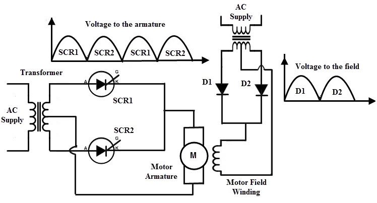
During the positive half cycle of the input, SCR1 is forward biased and when the triggering pulse is given to the gate, SCR1 starts conducting. So the load current flows to the DC motor through SCR1. During the negative half cycle of the input, SCR 2 is forward biased and SCR 1 is reverse biased and hence SCR1 is turned OFF.
When the gate triggering is given to SCR2 , it starts conducting. By varying the trigger input to the respective SCRs the average output to the DC motor is varied and hence its speed is controlled.
AC Motor Control Using SCR
An AC induction motor speed is controlled by varying the stator voltage applied to it. The below figure shows the connection of SCR for varying the voltage applied to the stator of induction motor.
Each phase consists of two anti-parallel SCRs, one for positive peak and another for negative peak. Therefore, total six SCR configurations are used for producing the variable power.
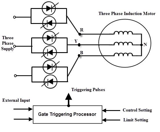
The input three phase AC supply is given to the three phase induction motor via these set of thyristors. When these SCRs are triggered with delayed pulses, the average voltage applied to the induction motor is get varied and hence the speed.
Advantages of Silicon Controlled Rectifier
- As compared with electromechanical or mechanical switch, SCR has no moving parts. Hence, with a high efficiency it can deliver noiseless operation.
- The switching speed is very high as it can perform 1 nano operations per second.
- These can be operated at high voltage and current ratings with a small gate current.
- More suitable for AC operations because at every zero position of the AC cycle the SCR will automatically switch OFF.
- Small in size, hence easy to mount and trouble free service.
Summary
- The Silicon Controlled Rectifier behaves like a switch with two states that is either non-conducting or conducting.
- There are three modes in which SCR operates. Those are forward blocking, forward conduction mode and reverse blocking mode.
- There are mainly two ways to turn ON the SCR that means either by increasing the voltage across the SCR beyond the break over voltage of the SCR or by applying a small voltage to the gate. The typical value of the gate is 1.5 V, 30 mA . If the gate current is increased the SCR will turn ON at much reduced supply voltage.
- The SCR cannot be turned OFF through the gate so to open the SCR, applied voltage must reduced to zero.
- Silicon Controlled Rectifier can be used for both AC and DC switching applications.

2 Responses
can u send me notes of SCR and IGBT
This is helpful to me be use it carries much of the important information.