In this tutorial, we will learn about some of the commonly known SCR Applications. The SCR Applications are Switching, Power Control in both AC and DC circuits, Over Voltage Protection etc.
Due to the wide variety of advantages, like ability to turn ON from OFF state in response to a low gate current and also able to switch high voltages, makes the SCR or thyristor to be used in a variety of applications. Let us understand these SCR Applications in detail below:
SCR Applications:
SCR applications include switching, rectification, regulation, protection, etc. The SCRs are used for home appliance control include lighting, temperature control, fan speed regulation, heating, and alarm activation.
For industrial applications, SCRs are used to control the motor speed, battery charging and power conversions. Some of them are explained below.
SCR as a Switch
The switching operation is one of the most important applications of the SCR. The SCR is often used as solid state relay and has more advantages than electromagnetic relays or switches as there are no moving parts in SCR.
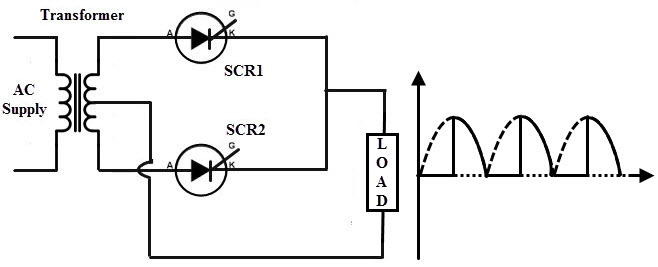
The below figure shows the application of an SCR as a switch to ON and OFF the power supplied to the load. The AC power supplied to the load is controlled by applying alternate triggering pulses to the SCR. The resistors R1 and R2 protect the diodes D1 and D2 respectively. The resistor R limits the gate current flow.
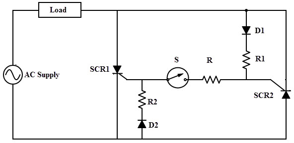
During the positive half cycle of the input, SCR1 is forward biased and SCR2 is reverse biased. If the switch S is closed, gate current is applied to the SCR1 through diode D1 and hence SCR1 is turned ON. Therefore, the current flows to the load through SCR1.
Similarly, during the negative half cycle of the signal, SCR2 is forward biased and SCR1 is reverse biased. If the switch S is closed, gate current flows to the SCR2 through diode D2. Hence the SCR2 is turned ON and the load current flows through it.
Therefore, by controlling the switch S the load current can be controlled at any desired position. It is observed that, this switch handles a few mill ampere current to control the several hundred ampere current in the load. So this method of switching is more advantageous than mechanical or electromechanical switching.
Power Control Using SCRs
The SCRs are capable to control the power transmitted to the load. It is often required to vary the power delivered to the load depends on the load requirements such as motor speed control and light dimmers.
Under such conditions power varying with conventional adjustable potentiometers is not a reliable method due to the large power dissipation. For reducing this power dissipation in high power circuits, SCRs are the best choice as power control devices.
AC Power Control using SCR
In AC circuits, the phase control is the most common form of SCR power control. In phase control, by varying the triggering angle alpha at the gate terminal, power control is obtained.
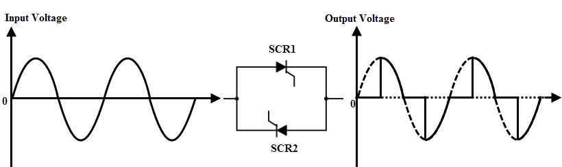
Below figure shows a full AC wave control circuit that illustrates the phase control method. Consider that the AC supply is given to the two anti-parallel SCRs. During the positive half cycle of the signal SCR1 conducts while in negative half cycle SCR2 conducts when proper gate pulses are applied to them.
By varying the firing angle to the respective SCRs, the turn ON times are varied. This leads to vary the power consumed by the load. In the below figure SCRs are triggered at delayed pulses (that means an increase of firing angle) results to decrease of the power delivered to the load.
The main advantage of the phase control is that the SCRs are turned OFF automatically at every current zero position of AC current. Hence, no commutation circuit is required to turn OFF the SCR.
DC Power Control using SCR
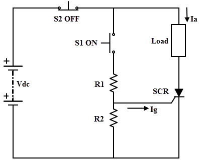
In case of a DC circuit, power delivered to the load is varied by varying the ON and OFF durations of the SCRs. This method is called as a chopper or ON-OFF control. Below figure shows the simple ON-OFF control of load using SCR.
It is also possible to switch the SCR at certain triggering frequency so that the current flowing to the load is varied. The example of such circuit is the PWM based SCR circuit to produce the variable output to the load.
It is possible to produce the variable DC power to the load by using phase control rectifier circuits. The average DC power delivered to the load is controlled by controlling the instant of turning ON of the SCR. Some of these rectifier circuits are given below.
Half Wave Rectifier
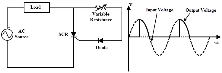
The circuit below shows the single phase half wave rectifier circuit using SCR. A diode in series with the variable resistor is connected to the gate which is responsible to trigger the SCR.
- During the negative half cycle of the AC input signal, the SCR is reverse biased. Hence, no current flows through the load.
- During the negative half cycle of the input, SCR is forward biased. If the resistor is varied such that the minimum triggering current is applied to the gate, then the SCR is turned ON. Hence the current starts flowing to the load.
- If the gate current is higher, the supply voltage at which the SCR is turned ON will be lesser. The angle at which the SCR starts conducting is referred as firing angle. For this rectifier circuit, firing angle can be varied during the positive half cycle only.
- Therefore, by varying the firing angle or gate current (by changing the resistance in this circuit), it is possible to make the SCR conduct part or full positive half cycle so that the average power fed to the load get varied.
Full Wave Rectifier
In a full wave rectifier, both positive and negative wave of the input supply are rectified. Hence, compared to the half wave rectifier, the average value of the DC voltage is high and also ripple content is less. The below figure shows the full wave rectifier circuit consisting of two SCRs connected with centre tapped transformer.
• During the positive half cycle of the input, SCR1 is forward biased and SCR2 is reverse biased. By applying the proper gate signal, SCR1 is turned ON and hence load current starts flowing through it.
• During the negative half cycle of the input, SCR2 is forward biased and SCR1 is reverse biased. With a gate triggering, SCR2 is turned ON and hence the load current flows through the SCR2.
• Therefore, by varying the triggering current to the SCRs, the average power delivered to the load is varied.
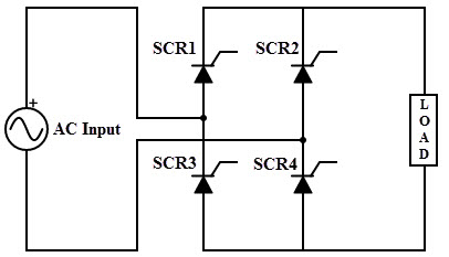
Full Wave Bridge Rectifier
Instead of using a centre tapped transformer, it is also possible to use four SCRs in a bridge configuration to get the full wave rectification. During the positive half cycle of the input, SCR1 and SCR2 are in conduction. During the negative half cycle, SCR3 and SCR4 are in conduction. The conduction angle of each thyristor is adjusted by varying the respective gate currents. And hence, the output voltage across the load is varied.
Over voltage Protection using SCR
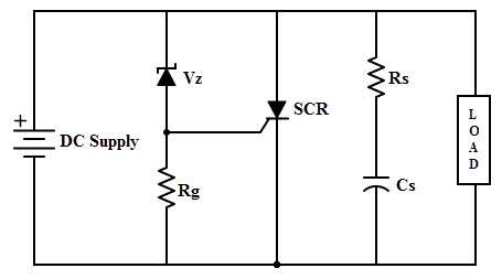
Due to the fast switching action of the SCR, one of the common SCR Applications is that it can be employed as a protecting device. The circuit used for the protection against over voltages is referred as Crowbar circuit.
The figure below shows the crowbar circuit using SCR. This crowbar circuit is connected across the circuit or load which is to be protected. This circuit consists of SCR which is triggered by zener diode arrangement. This zener diode is selected in such a way that under normal operating condition, it acts as an open switch.
So, the voltage across the resistor is zero and hence the SCR remains in OFF state.
Whenever the voltage of the supply source exceeds the specified limits, zener diodes starts conducting and a sufficient voltage appears across the resistor. This drives the SCR into conduction mode. The voltage drop across the SCR is reduced as it is in conduction mode and thus load is protected from the over voltage.

4 Responses
scr as a switch
values of scr , diode and resistance please give me reply
please mention the value and explain once with calculation with formulas.
Plz give me the values an formulas
Thanks for these edifying information and need more of these tutorials