In modern solar tracking systems, the solar panels are fixed on a structure that moves according to the position of the sun.
Let us design a solar tracker using two servo motors, a light sensor consisting of four LDRs and Arduino UNO board.
Arduino Solar Tracker Circuit Diagram
![]()
The circuit design of solar tracker is simple but setting up the system must be done carefully.
Four LDRs and Four 100KΩ resistors are connected in a voltage divider fashion and the output is given to 4 Analog input pins of Arduino.
The PWM inputs of two servos are given from digital pins 9 and 10 of Arduino.
Components Required
- Arduino UNO
- Servo Motor
- Light Sensors
- LDR
- Resistors
Arduino Solar Tracker Working
LDRs are used as the main light sensors. Two servo motors are fixed to the structure that holds the solar panel. The program for Arduino is uploaded to the microcontroller. The working of the project is as follows.
LDRs sense the amount of sunlight falling on them. Four LDRs are divided into top, bottom, left and right.
For east – west tracking, the analog values from two top LDRs and two bottom LDRs are compared and if the top set of LDRs receive more light, the vertical servo will move in that direction.
If the bottom LDRs receive more light, the servo moves in that direction.
For angular deflection of the solar panel, the analog values from two left LDRs and two right LDRs are compared. If the left set of LDRs receive more light than the right set, the horizontal servo will move in that direction.
If the right set of LDRs receive more light, the servo moves in that direction.
Setup
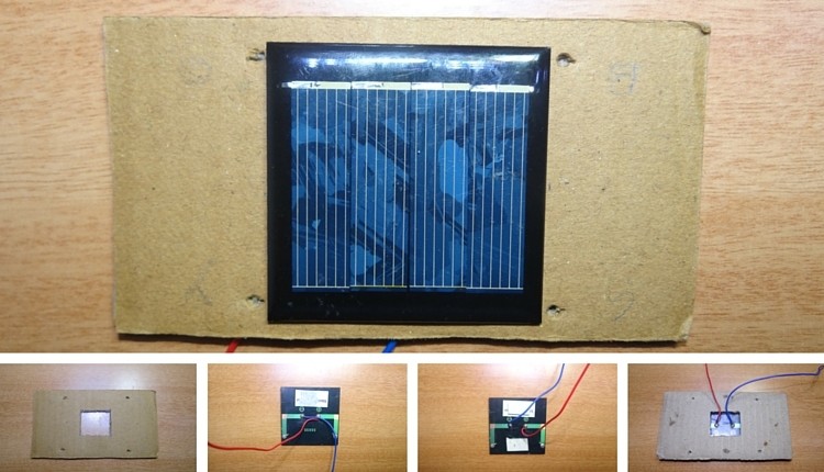
Step-1
- Take cardboard. Make a hole in the middle and four holes on four sides so that LDR fit into that.
- Stick the solar panel to the cardboard and bring two wires of the panel out as shown.
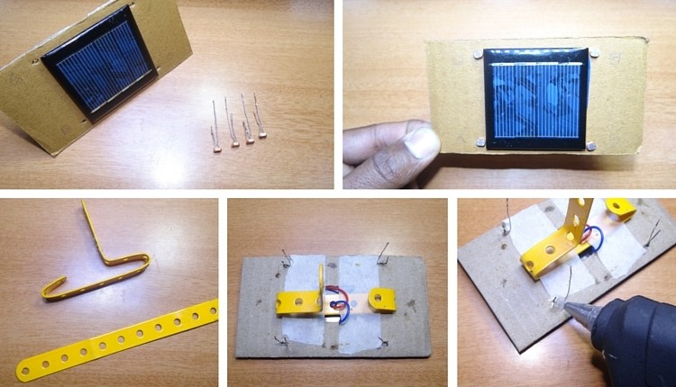
Step 2
- Now cut one of the two leads of the LDR so that one lead is shorter and other is longer.
- Insert these four LDRs into four holes as shown.
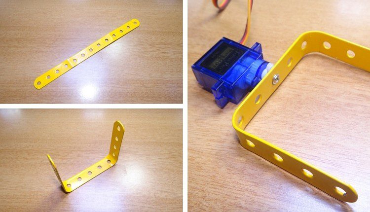
- Bend the straight Perforated metal strip as shown below.
- Place the bent metal strip on the back side of the cardboard
- Apply glue to the LDR to fix them firmly.
Step 3
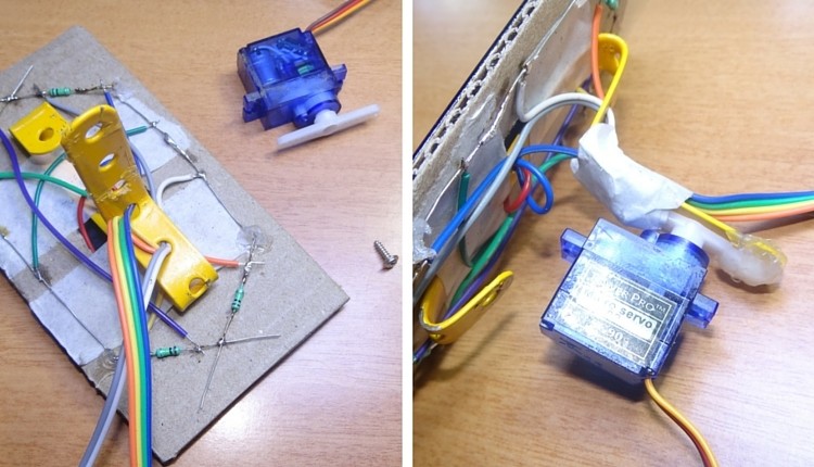
- Solder the two leads of LDR as shown
- To the other ends of LDR Solder resistors of 10k ohm
- Join the four leads of the 4 LDRs by connecting with a wire.
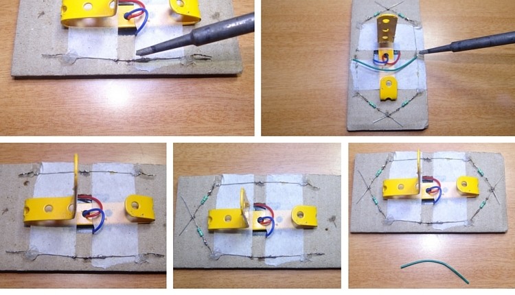
Step4
- Now take a bus wire.This is used to connect the Outputs of four LDRs to Arduino board.
- Insert it into metal strip as shown in the image.
- Now Solder the four wires to four LDRs at any point between LDR and resistor.
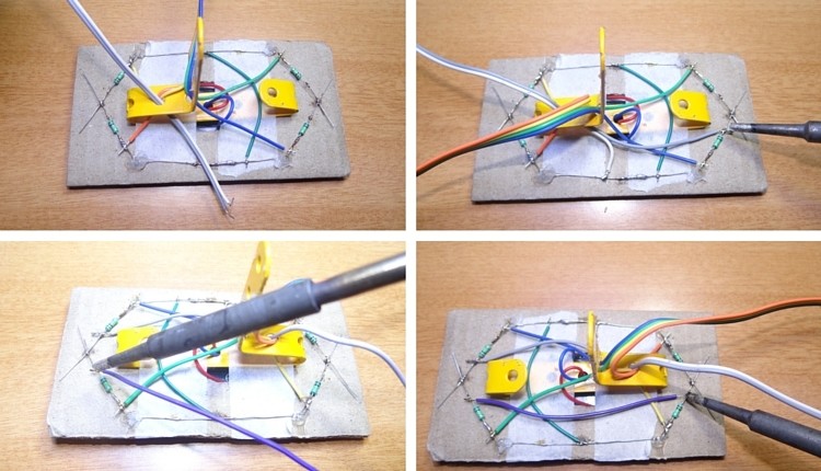
Step 5
- Insert another two wire bus into the perforated metal strip as shown.This is used for supplying Vcc and GND to LDR circuit.
- Solder one wire to the leads of LDRs which are connected to resistors and other wire to the other leads.
- Short the leads of LDRs connected to resistors using a wire as shown.
Step 6
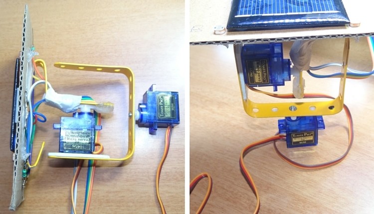
- Now connect a servo motor to the Perforated metal strip using Screw.
- Apply glue to the servo to fix it firmly.
 Step 7
- Take another straight Perforated metal strip and bend it as shown in the figure.
 Step 8
- Now place the set up of solar panel and first servo motor to the metal strip of second servo motor as shown.
Project Code
If you are the one who loves to craft inspiring projects then Arduino solar tracker is for you. But still, if you are unable to design projects on your own that may be due to the lack of components or some other issues. To them, we bought the Best Solar Panel Kits for Homes that completely satisfies their requirements.
In this article, detailed information on solar panels like prices, power usage and performance is given for the convenience of users. Make a try with these wonderful solar panel kits to install them in your homes.

101 Responses
How much power the panel is producing and how much the servos are consuming?
This designed only for tracking sun and increasing its efficiency….Power of the solar panel is not considered…Servo motors used here consume very less power..They are powered from arduino board it self
Good
Can you please explain the steps for the programm….what do you declare of each entry into the programm?
Thank you in advanceQ!!!!!
good job
Nice project – thanks for sharing
what is Perforated metal measurements?
Page excellent , and excellent projects for beginners im a student and I think this is awesome because we need projects like this to be best. congratulations !
greetings to you sir and all on this site. please i want to work this project in my school. as my second year project in the university. What i want to ask is the solar panel tracker tracking the sun light intensity for other panels on 100w or others?thank you will be waiting for your reply
sir,if one has about 10 100w solar panels how can he connect the solar tracker,and how many connection of the solar straker does he need
Hello,
I tried makin the project bt d motors r moving very slow. They r not moving as fast as given in d video. I tried changin d servo motor bt d isssue remains d same. Cn der b ny oder prob
Hi, Anyone else noticed that the diagram might be wrong? It states 100k resistors, however i believe it should be 10k? 10k is also listed in the picture text step 3
Is there any calculation required for angle by which servo motor will move…?
can anyone please elaborate steps 4 and 5?
Good work, Which kind of servo motors are used ?
good
What is the cost of this project?
Where can i found the metal strip that is used in the project?
Hey I want the advantage and application of Arduino based solar tracker
Is there a youtube video showing how it works??containing perhaps more details?
You can see the video in the PAge itself
Thanks a lot!
Sir plz help I connected ckt as per ur instructions but .. Model is not working
Hi, Please check the connections once again. Try to calibrate the servos and LDR before connecting.
Hi, the arduino code has to change. As it is now, it is not possible to use the High/Low limits for servos…
The limits for Servo motors are made as per our convenience. Please calibrate the servos and change the max limits for the servos.
hey , i thought that too, my motors arent working , pls can u send me the corrected program
.pls the corrected code?
Sir, when I When I combined that source code with code for ESP8266 to display the value of the LDR sensor on Thingspeak, the servo motor is not running. how to handle it? Thanks before.
Hi, we haven’t tried this particular setup. We will try it and update as soon as possible.
thanx
its can not work properly plz help me in this
can you make a flow chart of this system ?
How about using just two analog inputs? Place two LDR’s on adjacent sides of the solar panels, not in the corners. One of the LDR’s works as a pull-up resistor and the other one works as the pull-down resistor.
More thoroughly: connect 5V to the top side LDR, connect the other leg of the top side LDR to analog pin A0, connect A0 further to the bottom side LDR. And the other leg of the bottom side LDR to ground. Now, when the top gets more light, A0 voltage rises. When panel twists upwards, the bottom LDR gets more light and A0 drops back to the middle voltage. Similar connection for left and right and A1.
This setup might need additional resistors to assure that when the panel faces the sun and both LDR’s get equally much light, the total resistance won’t drop too low to draw too much current from the 5V. So you still need your 4 resistors, but you need only two analog input ports and the programming might become easier.
Hi, This is actually a great idea and you can complete with just two Analog pins. Try to share your work (in case you have implemented) so that others can benefit from it.
@Johan, I was thinking the same thing.
@Anusha, thanks for a nicely done simple project!
im using motor Ls-3006, once i connected everything and uploaded the program,
the motor keep rotating (more the 180 degree). How can i control the rotation angle of the motor
Hi, You should use maximum limits for both sides (left and right) and restrict your servo to rotate with in those limits.
For this code, are we supposed to put in any values? If yes, what should we put?
,servoh = servohori.read();
servov = servoverti.read();
Hi, By values, if you mean any user inputs, then we need to set the Servo motor limits for both the servos. servoh = servohori.read();servov = servoverti.read(); This statement returns the current position of the servo in the form of angle (between 0 and 180).
i used the code provided above but it giving me error .plz help me fast i have project on monday
Hi,What is the error you are getting?
Is it possible to run linear engines their 12V capabilities
Which compiler is used? the code wont work for atmel studio 7 unless more peripherals and initialization is added
Could the servos be replaced with 12V linear motors, and the power to them be 12V instead of 5V? I am new to this & looking to learn.
Thanks
How can i make this together with a data Logger and also what’s the code for that?
hi, may i know you are using 180 degrees or 360 degrees servo motor?
Hi, the servo motor can rotate approximately 180 degrees.
Hello sir ,
Can u please give us the parts required and their details .so we can do it easily
i want to provide power supply to arduino from battery or something else.so what should i do
hi,
how can i use dc motor for this project.
What is the power of resistor is it 10 k om or 100k ohm
what are the specifications for the LDR?
Hi, We have used a 5mm LDR (Minimum Resistance of 400Ω and Maximum Resistance of 1MΩ).
So it is working successfully??
can anyone tell me about all the components name and their rating so i can purchase them easily.
Motor is not moving as fast as given in the video.plz help
Can Another servo will work for this code instead of SG90
Yes. You can use MG90S.
Can any one send me the application of solar tracking system using the ardiuno uno…
Plzzz it’s urgent….
When I took light and push it to LDR the panel is not stopping.It has a little bit movements.If we take out the light the panel does not stay in the same position.Can anyone say reason?
plzz.. help me with the resistors at LDR is it 100k or 10k
or did they booth work .and how it impacts on analog read values …?
Please send advantages and applications
Super i done it
if u have done it can u please answer my few question that are:
which battery is used to give supply to the device.
and can u provide a proper discription of connections.
and also tell me about the specifications of material used.
Can you explain step 5 pls…
very…gooood!
Is there any rating for servo motors
Can you please help which one is the servo motor using for horizontal and vertical rotation in the diagram
I wants to use stepper motor instead of servo motor. So can I know which type of change in code is required?
Hello this nice project., but i want to know all the materials for that project??
Wich compiler did you chosen
Hi..
Good idea..
But i want to know about solar panel which u used for this prpject…
Plz provide full information
Hi,
Could you please send the specifications for the servo motors and the LDR’s.
what if I only want to make a single axis? which LDR are used? the top ones? I still confused about the movement of servo, which is the horizontal one
Where is the energy harnessed stored? And how will it be stored?
Hi there.
I am having difficulty externally powering the Ardiuno in this project. It seems to only work if I use the USB connection to my computer, but for the final project, I was hoping to use a 9V battery, I know the Ardiuno is equipped with a voltage regulator, so this shouldn’t be a problem, but the servos act extremely weird when the power supply changes.
If anyone has ideas please let me know.
thank you
Sir can you tell me how we download program code of this project to upload uno
CAN ANYONE PLEASE UPLOAD THE CONNECTIONS ON THE CARDBOARD PROPERLY , I AM NOT GETTIONG WHERE TO CONNECT VCC AND GROUND WIRES,.
.
in my setup the servos are rotating very slow than that of shown in video ? what can i don to increase its speed ? can decreasing resistance help?
do we have to use battery to provide supply to servo motors.
are u sure its working
Can anyone explain step 5 for VCC and gnd I’m stuck there
the panel moves with a jerk when operated. the motion is not smooth. what could be the possible reason?
can you please send the complete project details
components specifications
Which software is used for this coding?
Arduino IDE.
hi, can this project be built with a heliostat mirror other than a solar panel
Hi, why 100kohm resistor is used..?
what is the purpose of that resistor…? can you pls explain that
HOW MUCH POWER RATING IS SERVO MOTOR CAN USE. Please send the value such as power, current, voltage rating.
CAN I USE LDR MODULE INSTEAD OF LDR? SHOULD I NEED TO CHANGE THE PROGRAM
There doesn’t seem to be a sketch available to program the Arduino. Where might that be found?
Haw to calibrate servo & ldr? Plz reply…
may i know which servo motor is used for west east movements i.e., vertical movements from circuit diagram.
Sir please make video’s of this project ???????????
Yeah, A video or a pic of how the final product actually looks.
Can we use Arduino nano instead of Arduino uno?
Is the Solar Cell powering the Arduino or are we using a different battery for the Arduino.
can i use 9v supply
Analog inputs of the Photo resistor voltages can only be taken by A0,A1,A2,A3,A4,A5
NOT NORMAL DIGITAL PINS LIKE 1,2,4,6……
which linear actuators to use for solar tracker with real solar panels? THanks!