In this tutorial, we will learn about Sequential Circuits, what is sequential logic, how are sequential circuits different from combinational circuits, different types of sequential circuits, a few important Sequential Circuits Basics and many more.
Combinational Logic and Sequential Logic are the building blocks of Digital System Design. Combinational Circuits include Multiplexers, Demultiplexers, Encoders, Decoders, etc. whereas Sequential Circuits are Latches, Flip-flops, Counters, Registers etc.
To understand more about basics of Sequential Logic and all its elements like Clock, Triggering, Synchronous, Asynchronous Circuits etc. continue to read the following tutorial.
Introduction
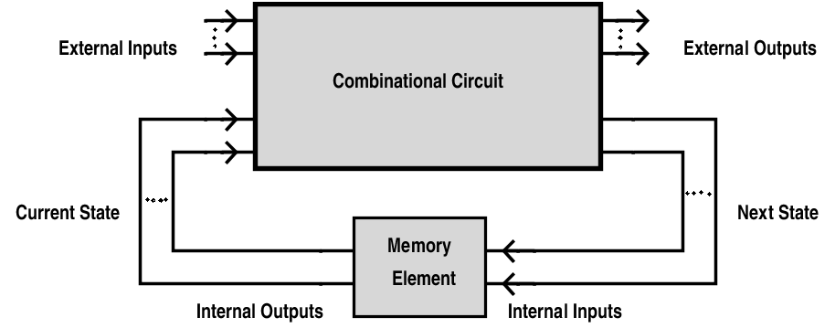
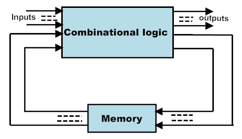
Sequential logic circuits are those, whose output depends not only on the present value of the input but also on previous values of the input signal (history of values) which is in contrast to combinational circuits where output depends only on the present values of the input, at any instant of time. Sequential circuit can be considered as combinational circuit with feedback circuit. Sequential circuit uses a memory element like flip – flops as feedback circuit in order to store past values. The block diagram of a sequential logic is shown below.

Sequential logic circuits are used to construct finite state machines, which are basic building block in all digital circuitry, and also in memory circuits. Basically, all circuits in practical digital devices are a mixture of combinational and sequential logic circuits.
Example:
Generally, we come across many counters in our daily life to count the number of objects .For example to count the number of audience entering or leaving an auditorium or to count number of vehicles in parking.In this when any person enters in to auditorium the counter increments its value depending on its present value. Similarly, it decrements its value depending on its previous and present value. So Counter retains the present state of the counter to do next operation.
This is analogous to sequential circuits which changes their state according to the previous and present signals.
Combinational Circuits vs Sequential Circuits
Output depends only on the present value of the inputs. Output depends on both the present and previous state values of the inputs
These circuits will not have any memory as their outputs change with the change in the input value. Sequential circuits have some sort of memory as their output changes according to the previous and present values.
There are no feedbacks involved. In a sequential circuit the outputs are connected to it as a feedback path.
Used in basic Boolean operations. Used in the designing of memory devices.
Implemented in: Half adder circuit, full adder circuit, multiplexers, demultiplexers, decoders and encoders. Implemented in: RAM, Registers, counters and other state retaining machines.
Clock Signal in Sequential Circuits
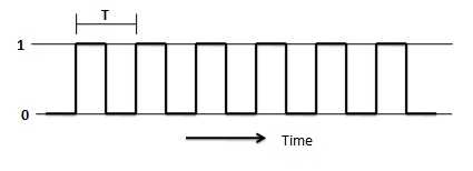
The clock signal plays a crucial role in sequential circuits. A clock is a signal, which oscillates between logic level 0 and logic level 1, repeatedly. Square wave with constant frequency is the most common form of clock signal. A clock signal has “edges”. These are the instants at which the clock changes from 0 to 1 (a positive edge) or from 1 to 0 (a negative edge).
Clock signals control the outputs of the sequential circuit .That is it determines when and how the memory elements change their outputs . If a sequential circuit is not having any clock signal as input, the output of the circuit will change randomly. So that they cannot retain their state till the next input signal arrives. But sequential circuits with clock input will retain its state till the next clock edge occurs.
Classification of Sequential Circuits
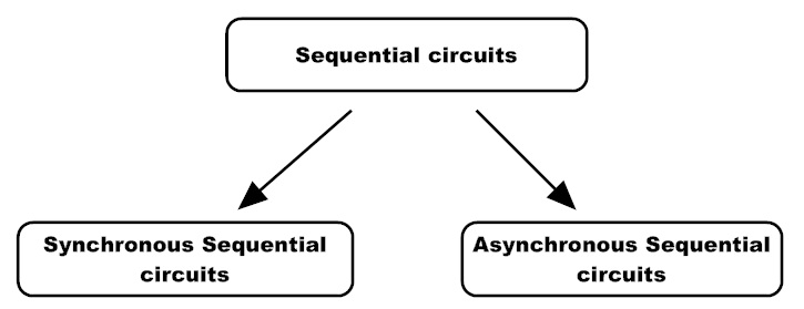
Based on the clock signal input, the sequential circuits are classified into two types.
- Synchronous sequential circuit
- Asynchronous sequential circuit
Synchronous Sequential Circuits
Definition:
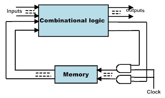
In Synchronous sequential circuit, the output depends on present and previous states of the inputs at the clocked instances. The circuits use a memory element to store the previous state. The memory elements in these circuits will have clocks. All these clock signals are driven by the same clock signal.
- Using clock signal, state changes will occur across all storage elements.
- These circuits are bit slower compared to asynchronous because they wait for the next clock pulse to arrive to perform the next operation.
- These circuits can be clocked or pulsed.
- The Synchronous sequential circuits that use clock pulses in their inputs are called clocked-sequential circuits. They are very stable.
- The sequential circuits that change their state using the pulse and these are called pulsed or un-clocked sequential circuits.
Where we use Synchronous Sequential Circuits??
• Used in the design of MOORE-MEALY state management machines.
• They are used in synchronous counters, flip flops etc.
Limitations of Synchronous Sequential Circuits
- All the flip – flops in synchronous sequential circuits must be connected to clock signal. Clock signals are very high frequency signals and clock distribution consumes and dissipated a large amount of heat.
- Critical path or the slowest path determines the maximum possible clock frequency. Hence they are slower than asynchronous circuits.
Asynchronous Sequential Circuits
Definition
The Sequential circuits which do not operate by clock signals are called “Asynchronous sequential circuits”.
- These circuits will change their state immediately when there is a change in the input signal .
- The Circuit behaviour is determined by signals at any instant in time and the order in which input signals change.
- They do not operate in pulse mode.
- They have better performance but hard to design due to timing problems.
- Mostly we use the asynchronous circuits when we require the low power operations.
- They are faster than synchronous sequential circuits as they do not need to wait for any clock signal.
Where we use Asynchronous Sequential Circuits??
These are used when speed of operation is important. As they are independent of internal clock pulse, they are operate quickly. so they are used in Quick response circuits.
- Used in the communication between two units having their own independent clocks.
- Used when we require the better external input handling.
Limitations of Asynchronous Sequential Circuits
- Asynchronous sequential circuits are more difficult to design.
- Though they have a faster performance, their output is uncertain.
Feedback in Sequential Circuits
Combinational circuits do not require any feed back as the outputs are purely dependent on the present value of the input. But in case of sequential circuits, the outputs are dependent on past values of the input along with present values. In order to involve memory element like a flip – flop, feedback must be introduced in the circuit. For example, consider a simple feedback circuit as shown below.
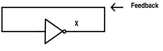
If 0 is the input to the inverter at an instance, this 0 will propagate and the output is 1. This 1 is fed back as input. This 1 will propagate and the output is 0. The process repeats and the result is a continuous oscillation of output between 0 and 1. There is no stable state in this scenario.
Now consider the following example of two inverters connected as shown.
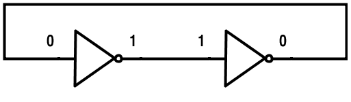
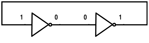
Here two inverters are connected back to back with the output of the second inverter fed back to input of first inverter. If 0 is the input to first inverter at an instance, it propagates through the first inverter and the output is 1. This 1 is input to second inverter and propagates through it. The output of the second inverter is 0 which is fed back to the first inverter. But the input to first inverter is already 0 and hence no change occurs. The circuit is said to be in a stable circuit. Another stable state can be obtained when the input to the first inverter is 1.
Latches and Flip flops
Latch
Latch is a basic building element in sequential circuits. Latches do not have any clock signal , that is they are asynchronous sequential circuits.
• Latches are made up of static gates.
• Latch is a bistable multivibrator i.e. it has two stable states and can switch between these states.
• Latches will have a feedback path from the output. Thus they change their output at any instant using the previous and present states of the input signals.
• When enabled, the output of the latch is continuously affected by its input i.e. the output changes immediately when the input changes. When disabled, the state of the latch remains constant i.e. it remembers its previous value. A clock or enable signal is used as a control signal.
• Latches continuously check all the inputs and correspondingly it changes its output when enabled.
Example: S-R latch is an example for simple latch.
Example: S-R latch is an example for simple latch.

Flip-Flop
The Flip-flop is also a building block of synchronous sequential circuits. It has two stable states. It can store one bit of information. Flip flops will have a clock signal. Their state changes depending on the clock pulse .These devices will is have two states and a feedback path .
- Flip-Flop is edge sensitive. They will change their state when the clock signal transition occurs from low to high or high to low.
- After the transition of clock signal from either 0 to 1 or 1 to 0 i.e. when the clock is at constant 0 or 1, the state remains unchanged even if the input changes.
Example: J-K Flip-Flop.
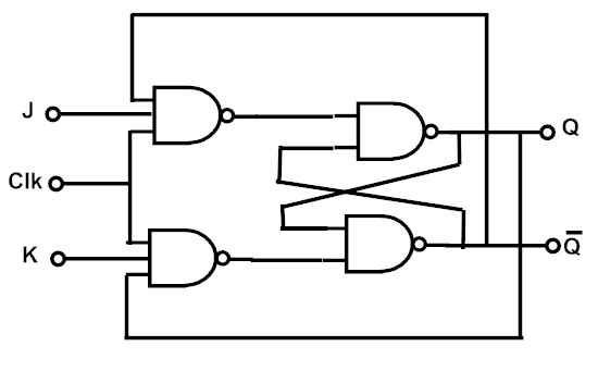
NOTE: The only difference between latches and flip – flops is that a latch is level sensitive to control signal (clock or enable) while a flip – flop is edge sensitive to the control signal (usually clock).
Triggering
Definition
The change in output of a flip flop can be done by bringing a small change in the input signal. This small change can be done with the help of a clock pulse. This clock pulse is known as a Trigger pulse.
A flip – flop is said to be “Triggered”, when a trigger pulse is applied to the input that brings changes in the output. Flip – flops are basic components in registers and counters, which store data in the form of multi – bit numbers. Number of flip – flops are connected to form a sequential circuit and all these flip – flops require trigger pulse. The number of trigger pulses applied to the input determines the number in a counter.
There are two type of triggering: Level Triggering and Edge Triggering
Level Triggering
The triggering process in which the change in the output state is according to the active level of inputs is called “Level Triggering”.
Level triggering is of two types, they are
1. High level triggering.
2. Low level triggering.
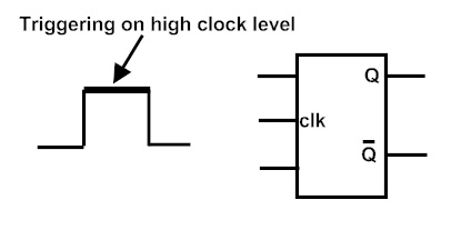
High Level Triggering
In High Level Triggering, the output of the flip – flop changes only when its enable input is at a high state i.e. logic high or logic 1. The symbolic representation of high level triggering is shown below.
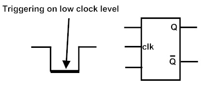
Low Level Triggering
In Low Level Triggering, the output of the flip – flop changes only when its enable input is at a low state i.e. logic low or logic 0. The symbolic representation of low level triggering is shown below. A low level triggering is usually identified by the bubble on the clock input.
Edge Triggering
In Edge Triggering, the output changes only when the inputs are present at either of the transitions of the clock pulse i.e. either from low to high (0 to 1) or from high to low (1 to 0).
Edge triggering is of two types, they are
1. Positive edge triggering.
2. Negative edge triggering.
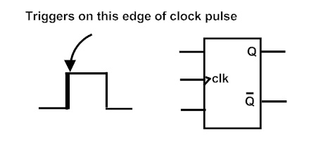
Positive Edge Triggering
In Positive Edge Triggering, the output changes only when the input is at the positive edge of the clock pulse input i.e. a transition from low to high (0 to 1).
Positive Edge Triggering method is used when a flip-flop is required to respond at low to high level transition state. The symbolic representation of positive edge triggering is shown below.
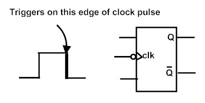
Negative Edge Triggering
In Negative Edge Triggering, the output changes only when the input is at the negative edge of the clock pulse input i.e. a transition from high to low (1 to 0).
Negative Edge Triggering method is used when a flip-flop is required to respond at high to low level transition state. The symbolic representation of negative edge triggering is shown below.
Edge Trigger Better Than Level Trigger
It is better to use edge triggering rather than level triggering. This is because level triggering might cause instability in the circuit for a particular case of a level triggered flip – flop, where the clock pulse is given to the input at the same time when the output of the flip – flop is changing. Feedback from the output to the input causes this instability. In order to avoid this instability, edge triggered flip – flops are used.

4 Responses
I am very thankful to u. This is really helpful to me understand the whole concept of sequential circuits.
Thankuw so much
Thanks this is very easy whole path of sequential circuits to understand briefly.
It was so helpful much appreciated 🤝🤝