In this tutorial, we will learn about SCR Turn OFF Methods. There are several ways to properly implement the SCR Turn OFF methods like Natural, Forced. In Forced Commutation, there are again several sub-categories like Class A, B, C, D, E. We will learn about all these different methods to properly turn OFF an SCR, different classes of Commutation, and also the Dynamic Turn OFF Characteristics of SCR.
Basics of SCR Turn OFF
In SCR Turn ON Methods, where we can see how to turn ON an SCR by applying an appropriate positive gate voltage between the gate and cathode terminals.
An important point to note here is that, unlike a transistor, where the collector to drain current flows as long as there is a small base current flowing (gate voltage in case of a MOSFET), an SCR doesn’t need any gate voltage to stay turned ON.
Even if the gate voltage is removed (after the SCR turns ON), the SCR doesn’t stop conducting. So, the gate has no control flow of current from anode to cathode and the SCR cannot be turned OFF through the gate terminal. An SCR can return to its forward blocking state from the forward conduction state only when the anode or forward current is reduced below the holding current level.
The turn OFF process of an SCR is called Commutation. Commutation means transfer of current from one circuit to another. Where have you heard of the term commutation and commutators before? In brushed DC Motors. Commutators are part of the brush assembly and are responsible for reversing the direction of current in the winding.
So, the commutation circuit for an SCR does s similar job by reducing the forward current to zero in order to turn OFF the SCR or Thyristor. However, even after the anode current drops to zero, the SCR may conduct again if a forward voltage is immediately reapplied.
So, to turn OFF a conducting SCR properly, the following conditions must be satisfied:
- The anode or forward current of SCR must be reduced to zero or below the level of holding current and then,
- A sufficient reverse voltage must be applied across the SCR to regain its forward blocking state.
When the SCR is turned OFF by reducing forward current to zero, excess charge carriers exists in different layers. To regain the forward blocking state of an SCR, these excess carriers must be recombined. So, to speed up the recombination process, a reverse voltage is applied across the SCR.
We know that an SCR, essentially, has only two states: ON State (or Conduction State) and OFF State (Blocking State). Also, the SCR doesn’t have any control on the load voltage and current (as it is just a switch). So, the only way to control the level of voltage and current is through the process of Turn ON and Turn OFF of the SCR.
Commutation is a critical process used in the turn OFF of SCR.
SCR Turn OFF Methods
An SCR is said to be ‘turned OFF’ if there is no flow of forward current and even if the SCR is once again forward biased (positive voltage at anode), the SCR will not conduct without any Gate Signal (using one of the SCR Turn ON Methods).
The reverse voltage, which causes to commutate the SCR, is called the Commutation Voltage. Depending on the type of switching of SCR (Cyclic or Sequential), the commutation methods are classified into two major types. They are:
- Natural Commutation
- Forced Commutation
Before discussing about different types of ACR Turn OFF Methods, there is an important quantity known as the Turn OFF Time of SCR which we have to understand.
Turn OFF Time of an SCR is the time between the moment anode current becomes zero and the moment SCR starts to block the forward voltage.
Natural Commutation
In natural commutation, the source of commutation voltage is the supply source itself. If the SCR is connected to an AC supply, at every end of the positive half cycle, the anode current naturally becomes zero (due to the alternating nature of the AC Supply). As the current in the circuit goes through the natural zero, a reverse voltage is applied immediately across the SCR (due to the negative half cycle). These conditions turn OFF the SCR.
This type of commutation is also referred to as Source Commutation, AC Line Commutation, or Class F Commutation. This commutation is possible with line commutated inverters, controlled rectifiers, cyclo converters and AC voltage regulators because the supply is the AC source in all these converters.
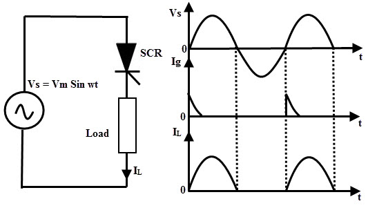
During the positive half cycle of the AC Supply, the load current flows normally. But, during the negative cycle, the SCR will turn OFF (due to momentary zero current and immediate negative polarity). For natural commutation to be effective, the SCR’s turn OFF time tOFF must be shorter than the duration of supply’s half cycle.
Forced Commutation
In case of DC circuits, there is no natural current zero to turn OFF the SCR. In such circuits, forward current must be forced to zero with an external circuit (known as Commutating Circuit) to commutate the SCR. Hence the name, Forced Commutation.
This commutating circuit consist of components like inductors and capacitors and they are called Commutating Components. These commutating components cause to apply a reverse voltage across the SCR that immediately bring the current in the SCR to zero.
Depending on the process for achieving zero current in the SCR and the arrangement of the commutating components, Forced Commutation is classified into different types. They are:
- Class A – Self Commutation by Resonating the Load
- Class B – Self Commutation by Resonating the Load
- Class C – Complementary Commutation
- Class D – Auxiliary Commutation
- Class E – Pulse Commutation
such as class A, B, C, D, and E. This commutation is mainly used in chopper and inverter circuits.
Class A Commutation
This is also known as Self Commutation by Resonating the Load or simply the Resonant Commutation. In this commutation, the source of commutation voltage is in the load. The commutating components are L and C and the Capacitor can be connected either in parallel or in series with the load resistance RL as shown below.
There are also waveforms of SCR current, voltage and capacitor voltage.
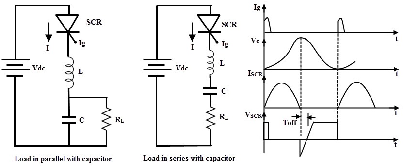
The value of load resistance and the commutating components are selected in such a way that they form an under-damped RLC resonant circuit. When the circuit is applied with a DC Source, the forward currents starts flowing through the SCR and during this period, the capacitor is charged up to the value of Vdc. The current in the circuit will be either of the two waveforms shown below, depending on how the load is connected to the capacitor (parallel or series).
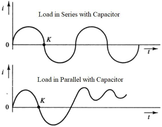
When conducting, the current in the SCR is the charging current of the capacitor. From the waveforms, it is clear that the current becomes zero at the point ‘K’. At this point, the SCR turns OFF.
The resonant frequency of the circuit, which depends on the Commutation Components L and C and also on the load resistance, determines the time for switching OFF the SCR.
Class A Commutation method is simple and reliable and is usually used in high frequency operations i.e., frequencies in the range of 1000 Hz and above due to the high values of L and C components (as they carry the full load current). This type of commutation is generally used in Series Inverters.
Class B Commutation
This is also a self commutation circuit in which commutation of SCR is achieved by a resonating LC Circuit. But the main difference between Class A and Class B Commutation is that the LC resonant circuit is connected across the SCR but not in series with the load as in case of Class A Commutation. As a result, the commutating circuit and the L and C components in it doesn’t carry the load current.
The following image shows the Commutating Circuit and also the waveforms associated with Class B Commutation.
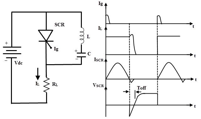
When a DC supply is applied to the circuit, the capacitor charges up to Vdc, with an upper plate positive and lower plate negative. When the SCR is triggered, the current flows in two directions: one is through Vdc+ – SCR – R – Vdc– and the another one is the commutating current (IC) through L and C components.
When the SCR is turned ON, the capacitor starts discharging in the path C+ – L – SCR – C–. When the capacitor is fully discharged, it starts charging with a reverse polarity. As a result of the reverse voltage, a commutating current IC, will flow in the opposite direction of the load current IL.
When the commutating current IC becomes higher than the load current, the SCR will automatically turn OFF and the capacitor charges with its original polarity (through Inductor and Load).
From the above explanation, we can understand that the SCR is turned ON for some time and then automatically turned OFF for some time. This is a continuously repeating process. The frequency of ON/OFF state depends on the values of L and C in the commutating circuit. This type of commutation is mostly used in chopper circuits.
Class C Commutation
In this commutation method, the main SCR (which is to be commutated) is connected in series with the load and an additional or complementary SCR is connected in parallel with the main SCR. Hence, this method is also called as Complementary Commutation.
In this, SCR turns OFF with a reverse voltage of a charged capacitor. The figure below shows the complementary commutation with appropriate waveforms.
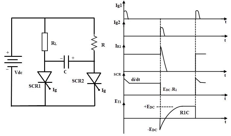
Initially, both SCRs are in OFF state so the capacitor voltage is also zero. When the SCR1 or main SCR is triggered (by applying a pulse to its gate), current starts flowing in two paths: one is the load current IL through Vdc+ – RL – SCR1 – Vdc– and the other is the charging current of the capacitor IC through Vdc+ – R1 – C+ – C– – SCR1 – Vdc–. Therefore, the capacitor starts charging up to the value of Vdc, with the polarity as shown in the above image.
When the SCR2 is triggered (by applying a pulse to its gate), it is turned ON. As a result, the negative polarity of the Capacitor is applied across the anode of SCR1 and the positive polarity is applied to cathode of SCR1.
This will cause a reverse bias across the main SCR (SCR1) and hence, it turns OFF. Now, the capacitor charges through the load and the path is Vdc+ – RL – C+ – C– – SCR2 – Vdc–. The polarity of the capacitor is now reversed.
If the SCR 1 is triggered once again, the discharging current of the capacitor turns OFF the SCR2 and the process repeats.
This commutation is mainly used in single phase inverters with a center tapped transformers. The McMurray Bedford inverter is the best example of this commutation circuit. This is a very reliable method of commutation and it is also useful even at frequencies below 1000 Hz.
Class D Commutation
This is also called as auxiliary commutation because it uses an auxiliary SCR to switch the charged capacitor. In this, the main SCR is commutated by the auxiliary SCR. The main SCR with load resistance forms the power circuit while the diode D, inductor L and SCR2 forms the commutation circuit.
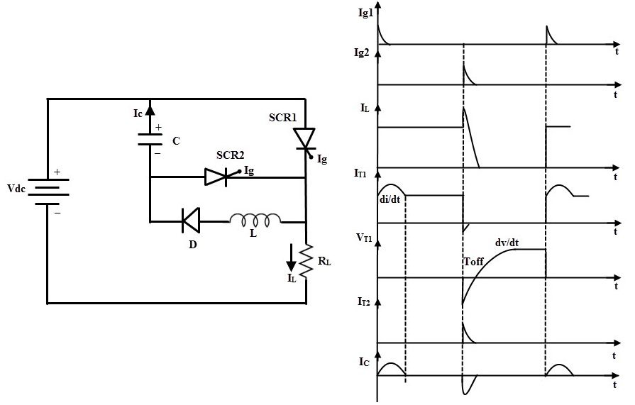
When the supply voltage Vdc is applied, both SCRs are in OFF state and hence the capacitor voltage is zero. In order to charge the capacitor, SCR2 must be triggered first and the capacitor charges through the path Vdc+ – C+ – C– – SCR2 – RL – Vdc–.
When the capacitor is fully charged, the current flow decreases and since the SCR2 is in series with the capacitor, it turns OFF. If the SCR1 is triggered, the current flows in two directions: one is the load current IL through Vdc+ – SCR1 – RL – Vdc– and another one is commutation current (due to capacitor discharge) through C+ – SCR1 – L – D – C–.
As soon as the capacitor discharges completely, its polarities will be reversed but the presence of diode prevents the reverse discharge. When the SCR2 is triggered, capacitor starts discharging through C+ – SCR2 – SCR1 – C–. When this discharging current is more than the load current, the SCR1 gets turned OFF.
Again, the capacitor starts charging through the SCR2 to a supply voltage Vdc and then the SCR2 is turned OFF (after capacitor is fully charged). Both the SCRs are now turned OFF and the above process is repeated.
This commutation method is mainly used in inverters and also used in the Jone’s Chopper Circuit.
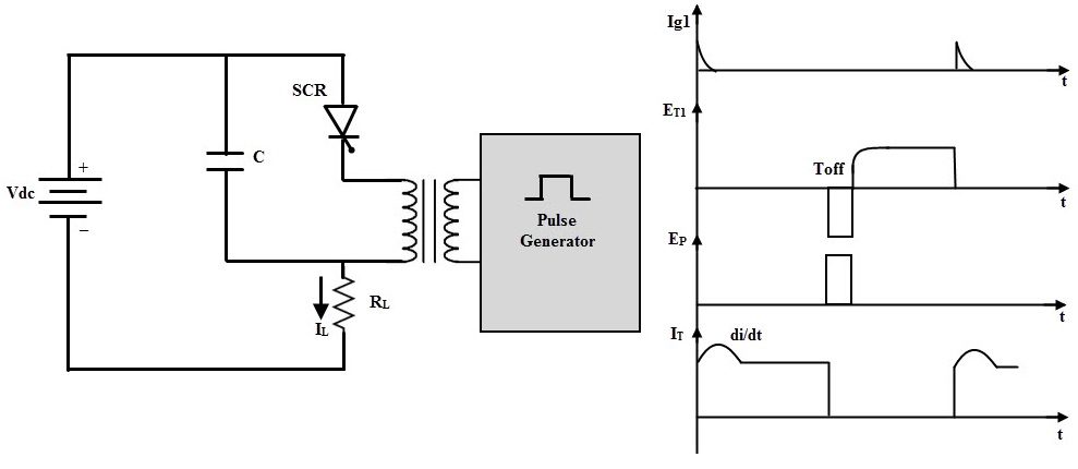
Class E Commutation
This type of Commutation is also known as External Pulse Commutation. In this, an external pulse source is used to produce the reverse voltage across the SCR. The circuit below shows the Class E commutation circuit, which uses a pulse transformer to produce the commutating pulse. The transformer is designed with tight coupling between the primary and secondary and also there is a small air gap in the transformer so that it doesn’t get saturated when the pulse is applied.
If the SCR needs to be commutated, pulse is applied whose duration is equal to or greater than the turn OFF time of the SCR.
If the SCR is triggered, load current flows through the pulse transformer. If a pulse (of potential VP) is applied to the primary of the pulse transformer, a voltage is induced in the secondary of the pulse transformer.
This induced voltage is applied across the SCR with a reverse polarity (–VP) and hence the SCR is turned OFF. The capacitor offers a very low or zero impedance to the high frequency pulse.
Dynamic Turn OFF Switching Characteristics
The transition of an SCR from forward conduction state to forward blocking state is called as turn OFF or commutation of SCR. As we know that once the SCR starts conducting, the gate has no control over it to bring back to forward blocking or OFF state.
To turn OFF the SCR, the current must be reduced to a level below the holding current of SCR. We have discussed various methods above to turn OFF the SCR in which SCR turn OFF is achieved by reducing the forward current to zero. But if we apply the forward voltage immediately after the current zero of SCR, it starts conducting again even without gate triggering.
This is due to the presence of charge carriers in the four layers. Therefore, it is necessary to apply the reverse voltage, over a finite time across the SCR to remove the charge carriers.
Hence, the turn OFF time is defined as the time between the instant the anode current becomes zero and the instant at which the SCR retains the forward blocking capability. The excess charge carriers from the four layers must be removed to bring back the SCR to forward conduction mode.
This process takes place in two stages. In a first stage, the excess carriers from outer layers are removed and in second stage excess carriers in the inner two layers are to be recombined. Hence, the total turn OFF time tOFF is divided into two intervals: reverse recovery time trr and gate recovery time tgr.
tOFF = trr + tgr
The figure below shows the switching characteristics of SCR during turn ON and OFF. The time t1 to t3 is called as reverse recovery time. At the instance t1, the anode current is zero and builds up in the reverse direction, which is called as reverse recovery current. This current removes the excess charge carriers from outer layers during the time t1 to t3.
At instance t3, junctions J1 and J3 are able to block the reverse voltage but, the SCR is not yet able to block the forward voltage due to the presence of excess charge carriers in junction J2. These carriers can be disappeared only by the way of recombination and this could be achieved by maintaining a reverse voltage across the SCR.
Hence , during the time t3 to t4, the recombination of charges takes place and at the instant t4, junction J2 completely recovers. This time is called gate recovery time tgr.
- From the figure, the turn OFF time is the time interval between the t4 and t1. Generally, this time varies from 10 to 100 microseconds. This turn OFF time tOFF is applicable to the individual SCR.
- The time required by the commutation circuit to apply the reverse voltage to commutate the SCR is called the circuit commutation time (tC). For a safety margin or reliable commutation, this tC must be greater than the tOFF otherwise commutation failure occurs.
- The SCRs, which have slow turn OFF time, usually between 50 to 100 microseconds, are called as converter grade SCRs. These are used in phase controlled rectifiers, cyclo converters, AC voltage regulators, etc.
- The SCRs, which have fast turn OFF time, usually between 3 to 50 microseconds, are inverter grade SCRs. These are costlier compared to converter grade and are used in choppers, force commutated converters and inverters.
Conclusion
A complete tutorial on SCR Turn OFF Methods. You learned the need for turning OFF SCR, different ways to turn OFF an SCR, commutation and different types of commutation. If you have any queries, feel free to share them with us in the comments section below. We will help to resolve them promptly.

18 Responses
Excellent article
Thank you easy to learn and easy to write foor exams
Also unable to see dynamic characteristics image please check
Good.Job
This is a great site for learning.. these topics are described very complicatedly in books. Thanks
So esay explain thanks gentle man
Its too good ….explanation
more helpful thank u sir
it was very helpful
except the line commutation is not added in that list.
thnkx for providing such useful content in simpliest form. cause dis topic is described very difficult in books. thnkx a lot.
explanantion is very lucid & its very easy to understand .Thanks
V good work…
Easy to learn and write in exams
Very easy language as compare to books…..!
these topics are described very complicatedly in books. But you have provide in simple and conceptional topics.
Thanks sir.
It’s ba nice job …..it’s more clear and more lucid
Thanks for good work
Thank you this is really helpful , could you please also mention which type is used for high power , low power cicuits
Thanks for sharing this stuff
thank you very much for the help, the content was really informative and usefull