Have you ever tried to design a robot which can capture audio and video information from the surroundings and can be sent to the remote area? This article explains you how design a spy robot which can be controlled by the remote. The maximum controllable range is 125 meters. The remote has four switches to control the robot in four directions.
The robot senses the surroundings through the CCD camera and sends to the receiver through the Radio Frequency wireless communication. We have already studied how to establish RF communication in RF Remote Control Circuit for Home Appliances post. This circuit is also designed using such kind of technology.
Remote Operated Spy Robot Circuit Principle:
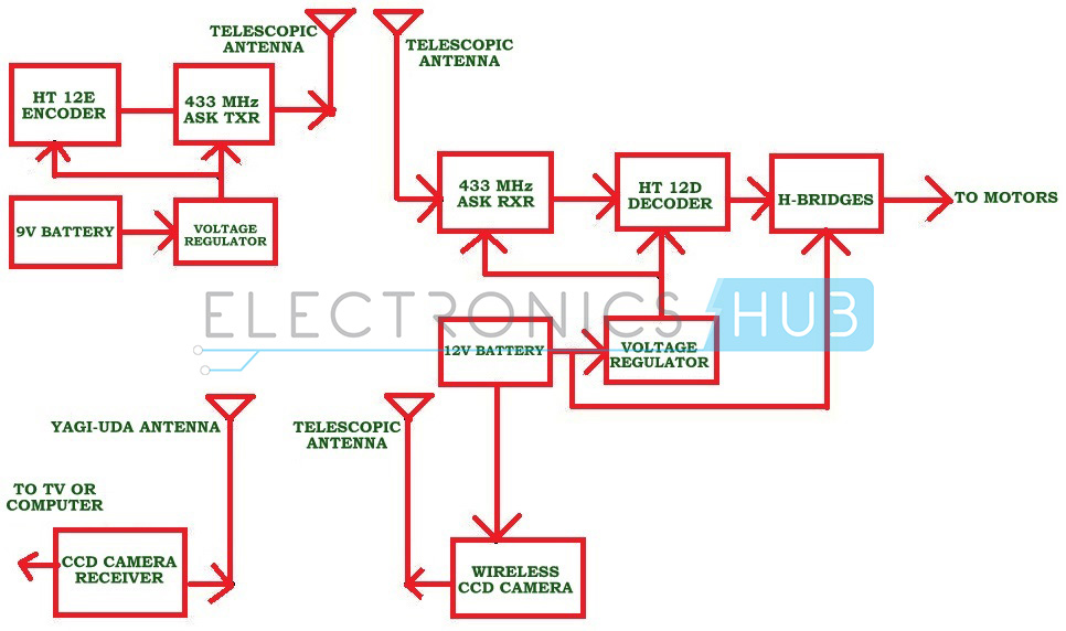
When we press any key in remote, the HT12E encoder generates 8 bit address and 4 bit data. Then ASK (Amplitude shift keying) transmitter sends 8 bit address and 4 bit data to the receiver. At the remote section DIP (dual inline package) switches are used to set 8 bit address. Receiver receives these 12 bit data and gives it to the HT12D decoder to decode the data. The decoded data is given to the L293D motor driver to rotate the robot motors.
Block Diagram of Remote Operated Spy Robot:
- HT12E encoder
- HT12D decoder
- RF 433 MHz Transmitter and Receiver
- L293D motor driver
- Wireless CCD camera
- push buttons – 4
- DC battery – 12V, 1.3 Ah
- 9V DC battery
- Robot
- Resistors – 33k,750k
- SPST switch – 1
- NOT gates – 4
Also read the related post: DTMF Controlled Robotic Vehicle
Remote Operated Spy Robot Circuit Diagram and Design:
Remote operated spy robot has mainly two sections, one is remote control section used to control the robot and other one is video transmission section used to transmit audio and video information.
Remote Control Section:
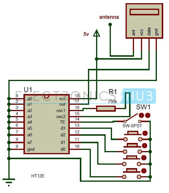
Here HT12E encoder reads the parallel data from the switches and gives this data to the RF transmitter serially. The operating voltage of this encoder is 2.4 to 12V. The RF 434 MHz Transmitter output is up to 8mW at 433.92 MHz frequency. This ASK transmitter accepts both linear and digital inputs and operating voltage is 1.2V to 12V DC. In remote section, SW1 is used to enable the transmission.
Video Transmission Section:
In this section, major components are wireless camera, RF receiver and Robot.
Wireless CCD Camera: The operating voltage of CCD camera is 12V DC. The supply for this camera is taken from the motors battery. The output signals of this camera are in the form of audio and video. These types of cameras are commonly available in the market.
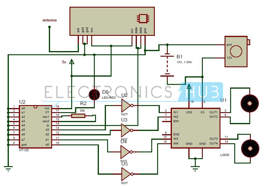
RF Receiver:
ASK receiver receives the serial data transmitted by the transmitter and gives it decoder to convert it to the parallel. This parallel data is given to the L293D motor driver IC to control the robot motors. Here LED D5 indicates the valid transmission.
L293D Motor Driver:
L293d is a Dual H-bridge motor driver. Used as a current amplifier since it takes low current control signal and provides higher current signal as output. This output signal is used to drive the motors.
This IC drives 2 motors simultaneously, both in forward direction and reverse direction. Motor 1 direction can be controlled based on logic inputs at IN1 and IN2. Motor 2 operations are controlled based on the inputs at IN3 and IN4. Here the motors are operated with the voltage applied at pin 8.
- IN1=0 and IN2=0 -> Motor 1 idle
- IN1=0 and IN2=1 -> Motor 1 Anti-clock wise direction
- IN1=1 and IN2=0 -> Motor 1 Clock wise direction
- IN1=1 and IN2=1 -> Motor 1 idle
- IN3=0 and IN4=0 -> Motor 2 idle
- IN3=0 and IN4=1 -> Motor 2 Anti-clock wise direction
- IN3=1 and IN4=0 -> Motor 2 Clock wise direction
- IN3=1 and IN4=1 -> Motor 2 idle
Here Vcc is the voltage applied for the internal operation of IC. VSS is the voltage applied to drive the motors. We can apply a maximum of 36V and 600mA to drive the DC motors. Enable pins EN1 and EN2 of motor driver IC must be high to drive the motors.
How to Operate Remote Operated Spy Robot:
- Give the connections as per the circuit diagram.
- Arrange the wireless CCD camera to the robot.
- Give the wireless camera receiver connection to the computer or TV.
- Now switch on the both robot and remote supplies.
- Control the spy robot using remote. Now you can observe the robot surroundings in your computer or TV.
Remote Operated Spy Robot Project Output Video:
https://www.youtube.com/watch?v=Mevb453_lXM
Remote Operated Spy Robot Applications:
- This spy robot is used to observe the behavior of wild animals where human beings cannot reach.
- Used in army applications to detect the bombs.
- Used in industries.
Remote Operated Spy Robot Limitations:
- This system does not work for longer distances.
- This is a theoretical circuit and may require some changes to implement practically.

17 Responses
hi are you sure that this circuit will work properly
im very interessted in this Project and i wandet to ask if you can say me if this works or if you could specify the remote section. thx in advance
i want to make this …….plz help me shortly..
i want to make this ………….plz tell me how to make …….
i wnat to make this for college mini project
I wanted to do this as mini project
i have connect the component but it is not working plz help
Please send me your report/thesis .I wanted to pick it up as FYP,
I like but please camponet and material shopyi contect no
Dear friend,
This site really provides great ideas for emerging engineers; wishes. My questions are.” Why have you mentioned ‘ROBOT’ as a component required? Isn’t the robot made up of the L293D motor driver, two motors and the battery as power source? If so, what kind of motor does it require? Can’t we replace the 4 NOT gates with a single IC7404? ” Hope you would clarify me soon.
Thanks in advance.
Here robot means robot chassis.First you should assemble the robot..In the Previous robots like line follower robot,DTMF Controlled robot,we have shown the assembling of robot .12v DC motors are used for the robot.Here We have connected batteries,motor driver separately so they are separately mentioned.yes you can use a not gate IC like 7404.Check in our video we have connected a single IC..
I have like it, would you plz sent me your report
i want to make this project and wanted to know the cost estimation.please provide me entire cost of this project and kindly provide me step by step connection detail,thank you.
Please send me some cctv projects.
i wanted to make this one.please provide me each step by step assembling process and connections.
i will be very greatfull to you.
I appreciate the information in your site
it’s my interesting project in my Future…….