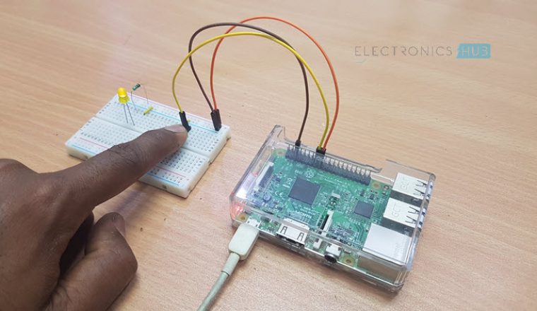
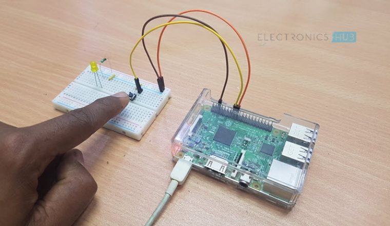
In this project/tutorial, we will see how to connect a simple Push Button to Raspberry Pi and how to accept input from the GPIO Pins of Raspberry Pi. Interfacing a Push Button with Raspberry Pi is very easy and the idea behind the project is to understand the concepts behind the interface.
Outline
ToggleOverview
As I have already mentioned in the How to Blink an LED using Raspberry Pi and Python Project, the GPIO pins of the Raspberry Pi is an important feature as they enable the Raspberry Pi to interface with external Physical Components like LEDs, Motors, Buttons, etc.
The GPIO Pins or General Purpose Input Output Pins, as the name suggests, can be configured as either Output Pin or an Input Pin.
If it is setup as an Output Pin, like in case of the LED Blinking Tutorial, the GPIO Pin drives an Output Device like an LED. On the contrary, if the GPIO Pin is configured as an Input Pin, it will read the incoming data from an external device, like a Button, in this scenario.
Before continuing, read HOW TO BLINK AN LED USING RASPBERRY PI?
GPIO of Raspberry Pi as Input
From the above statements, it is clear that if the Raspberry Pi wants to read the value from an external device, the corresponding GPIO pin must be declared as an Input Pin.
But when a GPIO Pin of the Raspberry Pi is declared as Input, it must be ‘tied’ to High or Low or else it is called as a Floating Input Pin. A Floating Input is a pin which is defined as input and left as it is.
Any Digital Input Pin is very sensitive and catches even the slightest changes and will pick up the stray capacitances from your finger, breadboard, air etc.
In order to avoid this, a Digital Input Pin must be tied to VCC or GND with the help of Pull-up or Pull-down resistors.
The following image shows an input pulled High and Low with the help of pull-up and pull-down resistors. In case of pull-up, the input will always read HIGH and when the button is pushed, it will read LOW.
In contrast, when an input pin is pulled-down, it will always read LOW and when the button is pressed, it will read HIGH.
This type of setup ensures that you can take reliable readings from the Switch or Button. Make sure that pin is not set as Output and pulled-High or pulled-Low as you might make a serious damage to the pins.
Basics of Push Button
Push Button is simplest of devices and it is the basic input device that can be connected to any controller or processor like Arduino or Raspberry Pi.
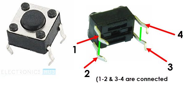
A push button in its simplest form consists of four terminals. In that, terminals 1 and 2 are internally connected with each other and so are terminals 3 and 4. So, even though you have four terminals, technically, you have only two terminals to use.
The above image shows a simple pushbutton and also highlights the internal connection.
Interfacing a Push Button with Raspberry Pi
As mentioned in the “GPIO as Input” section, when a GPIO pin is declared as Input, it must be connected to VCC or GND with the help of either a Pull-up resistor or a Pull-down resistor.
But, modern boards like Arduino and Raspberry Pi have a feature of Internal Pull-up or Internal Pull-down. With the help of this feature, you need not physically connect a pull-up or pull-down resistor to the input pin but configure it using the software.
Using this feature, the Pin will be pulled-High or Low from the inside of the chip.
While defining a GPIO pin of the Raspberry Pi as Input, add an additional statement in the program to activate the internal pull-up or pull-down.
In this project, by interfacing a Push Button with Raspberry Pi, we will read the status of the Input Pin and accordingly, turn ON or OFF an LED.
Circuit Diagram
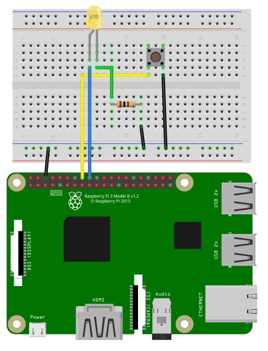
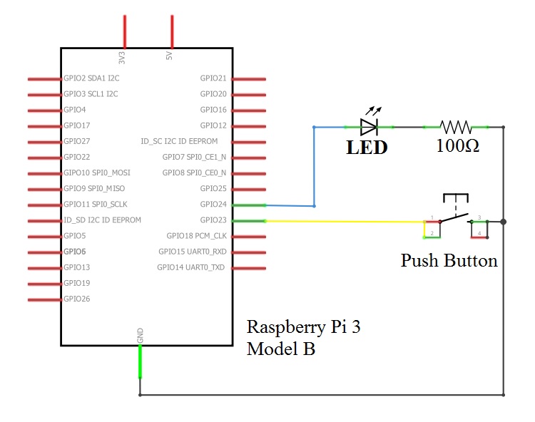
The following images show the circuit diagram of the Raspberry Pi Push Button Interface. The first image is based on the Fritzing Parts.
To get a clearer picture of the connections, the following wiring diagram from Fritzing will be helpful.
Components Required
- Raspberry Pi
- Push Button
- 5mm LED
- 100Ω Resistor (1/4 Watt)
- Mini Breadboard
- Connecting Wires
- Power Supply
Circuit Design
First, instead of using a four terminal push button, I have used a two terminal push button. This won’t make any difference. One terminal of the push button is connected to GND and the other terminal is connected to Physical Pin 16 (GPIO23) of Raspberry Pi.
A 5mm LED is used as an output device. The anode of the LED (long lead) is connected to Physical Pin 18 (GPIO24) of Raspberry Pi. The cathode of the LED (short lead) is connected to one terminal of a 100Ω Resistor.
The other terminal of the Resistor is connected to GND.
Code
Python is used as the programming language for this project. The Python Script is given below.
Working
The working of Raspberry Pi Push Button interface is very easy to understand. When the Python script is run, the Raspberry Pi initializes the Button Pin as input with internal pull-up and LED Pin as output.
Now, it waits for a change in state of the Input pin, which happens only when the button is pressed. If the button is pushed, Raspberry Pi will detect a LOW on the corresponding pin and activates the LED.
Applications
- Interfacing a Push Button with Raspberry Pi might not seem as a big project but it definitely helps us in understanding the concept of reading from Input pins.
- A similar concept can be applied to other input devices like different types of Sensors (PIR Sensor, Ultrasonic Sensor, Touch Sensor, and so forth).

