In this project, I will show you how to build a simple POV Display using Arduino Nano. This POV Display Project can be modified to display any text on a rotating LED Display. There are few Spinning LED Display modules available in the market but I thought why not make one myself.
This simple POV Display is implemented using Arduino Nano, few LEDs, an IR Sensor, couple of LiPo Batteries and few other components.
Introduction
We have already seen a project based on the concept of Persistence of Vision or simple called as POV. That project was the 8x8x8 LED Cube. In that project, there are 512 LEDs in the cube but as it is difficult to control all of them at once, I was controlling 64 LEDs at a time and POV does the rest of the magic.
Coming to this project, here the concept remains the same i.e. tricking our brain to believe that an object is present while it is actually not. A POV Display or a Rotating LED Display is a simple concept where we light LEDs at a variety of sequences in order to get an illusion of a Text being displayed.
I will present this project as a DIY type article with all the necessary things like circuit diagram, components, construction and code. First, let me begin with the circuit diagram of the POV Display project. But before that take a look at the output.
Output Video
Circuit Diagram of POV Display
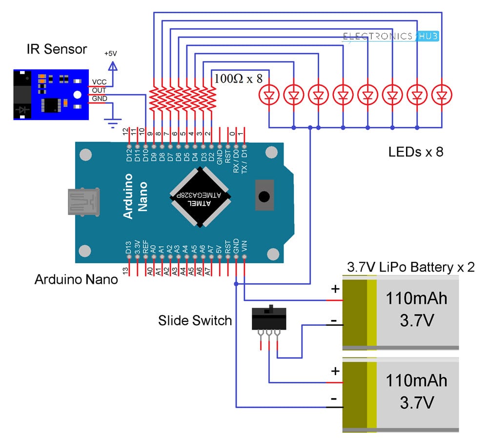
The following image shows the circuit diagram of the POV Display using Arduino Nano.
Components Required
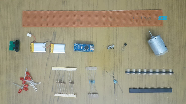
I will list out the circuit related components here. There are other tools and stuff you might require in order to construct this POV Display. I will mention those while I explain the construction.
- Arduino Nano
- LEDs x 8
- 100Ω Resistors x 8
- 3.7V LiPo Batteries x 2
- IR Sensor Module
- Slide Switch
- Perf Board
- 12V DC Motor
- Power Supply for Motor
Constructing the POV Display
Now, let me take you through a step-by-step construction of the POV Display.
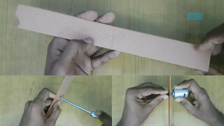
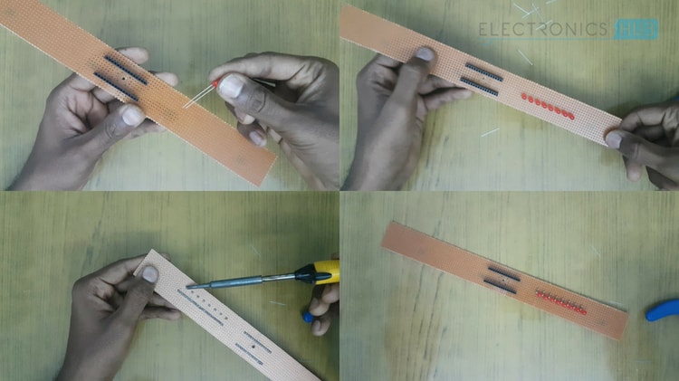
Getting the Base Board Ready
First, take a perf board as the one shown in the image and make a hole at the center to insert the motor’s shaft. In order to fix the motor to the board, I have used a pair of rubber holders on either side of the board.
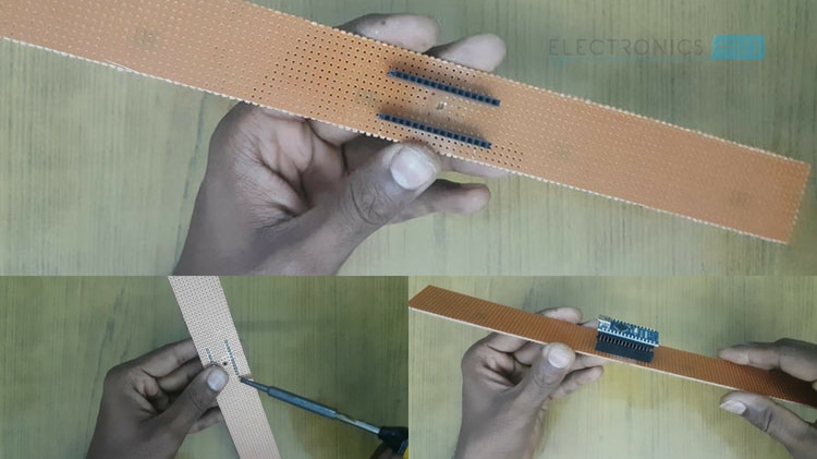
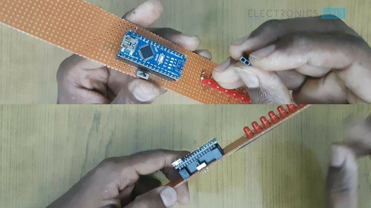
Mounting Arduino Nano
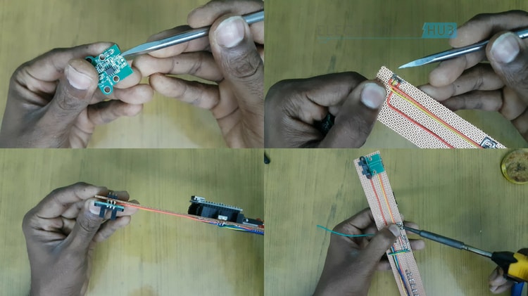
Solder two female header strips to insert the Arduino Nano. Position these headers with the hole for motor as center.
Solder LEDs and Resistors
Take 8 LEDs and place them in a row. Solder them to the perf board. Position these LEDs approximately at the center point between the edge of the board and hole drilled for inserting the motor.
After soldering all the LEDs, solder individual current limiting resistors to the anode terminals of the LEDs.
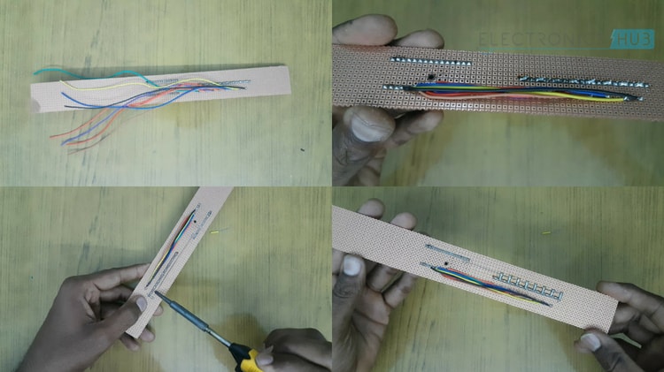
Connecting LEDs to Arduino
The other end of the resistor must be connected to Arduino. So, take a bunch of single gauge wire and connected the resistors to corresponding pin of the Arduino Nano.
Also, all the Cathode terminals the LEDs can be shorted with a long wire and connect this wire to the GND terminal of Arduino Nano.
Terminals for Battery
I have taken a pair of two-pin female headers and soldered it near the Arduino Nano. These headers are connected to individual batteries. The Positive terminal of first battery and Negative Terminal of second battery (through the headers) are connected to VIN and GND of Arduino Nano.
Additionally, a slide switch is connected between these two headers. Out of the three pins of the switch, the first one is left open, the middle pin is connected to negative of First Battery and the last pin is connected to Positive terminal of the second battery.
When the switch is in left position i.e. open, batteries are not connected and the power to the Arduino Nano is terminated. During this position, you can charge the batteries using a TP4056 Battery Charger with the help of those 2-pin headers.
Once the switch is move to the other position, the batteries are connected in series and 7.4V is supplied to Arduino Nano to power on the circuit.
Placing the Batteries
Two 3.7V LiPo Batteries are used in this project and both these batteries are placed on either side of the Nano board. Make the connections as mentioned in the above section.
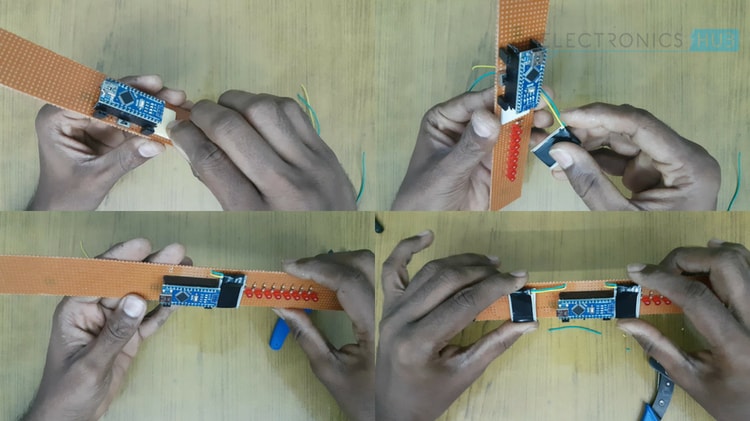
IR Sensor
A Transmissive Type IR Sensor is placed at the other end of the perf board but on the opposite side. It has three pins namely VCC, OUT and GND. VCC and GND are connected to +5V and GND of Arduino Nano while the OUT pin is connected to Pin 10.
Mounting Base
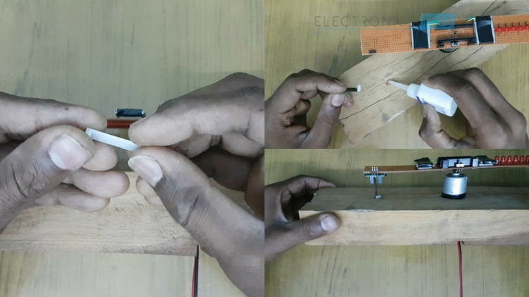
This completes the board part of the design. Next, lets make the stand or the base. Take a piece of wood and make a hole to insert the motor. Fix the perf board to the motor using holders.
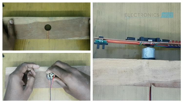
Next, take a small piece of plastic and fix is on the base such that it passes through the IR Sensor. The obstacle shouldn’t touch the IR Sensor or the perf board.
This finishes the complete construction of the POV Display using Arduino Nano.
Code
The code for the project is given below.
How POV Display Works?
Let me explain the working of the POV Display project with the help of a simple example. Consider you want to display the alphabet ‘B’. In order to display this character, the LEDs get turned on and off in a pattern over 5 steps. Each step is associated with a column of the LEDs and shown in the following image.
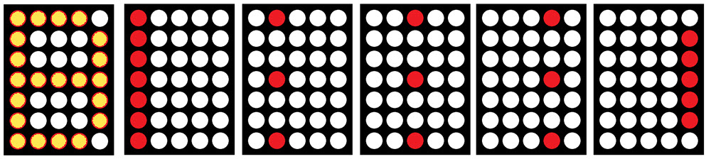
The delay between the switching of the columns is very less usually in the order of hundreds of microseconds (as you can see in the code).
In order to fix a starting point, the Arduino uses the IR Sensor as a reference i.e. when ever a signal from the IR Sensor is received, it starts displaying the text.

4 Responses
hi
thanks for your project
I just can to know that is POV
THANKING YOU
hai
when i compailed this prgm .it shows an compiling error to me like ”Arduino: 1.6.5 (Windows 7), Board: “Arduino Nano, ATmega328”
Build options changed, rebuilding all
sketch_sep13a.ino: In function ‘void loop()’:
sketch_sep13a:131: error: ‘PRINT_STRING’ was not declared in this scope
‘PRINT_STRING’ was not declared in this scope
This report would have more information with
“Show verbose output during compilation”
enabled in File > Preferences.
can u plz explain it
Hi, what is the purpose of using the IR sensor?
So the arduino knows where the spinning part is in the circle as it spins.. So it knows it takes X amount of time to go around 360 degrees so it needs to flash the leds at Y time and Z time… To make it look like letters.. Without the sensor the leds flashes wouldn’t look like the programmed characters..