In this project, we will see how to build an 8x8x8 LED Cube. There are many projects based on the 8x8x8 LED Cube and some of them became quite popular that it became a must-do project for many hobbyists.
Even we were planning on building an 8x8x8 LED Cube for quite some time and now we have finally finished building one and we are very happy with the end result.
The main purpose of this tutorial is to give you a brief idea about how to build an 8x8x8 LED Cube from scratch in a step-by-step manner.
NOTE: The work of “chr” from Instructables inspired us to build our own 8x8x8 LED Cube.
Overview
An 8x8x8 LED cube is a visual treat with 3D effects and patterns. It works on the concept of Persistence of Vision, a feature of the human eye which tricks our brain in to thinking that an object is present permanently at a place if it appear about 60 times in a second.
Since an 8x8x8 LED Cube consists of, well 8x8x8 = 512 LEDs, we cannot control all these 512 LEDs at once. What we can do is control 64 LEDs at a time at an extremely fast rate and trick our brain as if we were controlling all the 512 LEDs.
Sample Output Video
The following video shows a sample or a demo of the output of the 8x8x8 LED Cube.
Components, Tools and Parts Required for 8x8x8 LED Cube
- Arduino Nano
- LEDs (5mm) – 512
- 100Ω Resistors (1/4 Watt) – 64
- 1KΩ Resistors (1/4 Watt) – 16
- 10KΩ Resistors (1/4 Watt) – 8
- 2N2222 NPN Transistors – 16
- 74HC574 Octal D Flip-flop – 8
- 74HC138 3-to-8 Demultiplexer – 1
- 20-pin IC Socket – 8
- 16-pin IC Socket – 1
- 0.1µF Capacitor (104) – 9
- 1000µF Capacitor – 1
- 100µF Capacitor – 1
- 10µF Capacitor – 1
- Power ON LED – 1
- 100Ω Resistor for Power ON LED – 1
- 5V Power Supply
- Male Headers
- Female Headers
- Screw Terminals
- Connectors with Headers
- Ribbon Cables
- Standoffs
- Screws
- Connecting Wires
- Sunboard
- Cutter
- Stripper
- Solder Lead (lot of it)
- Soldering Iron
How to Build an 8x8x8 LED Cube?
Let us now take a look at how to build the 8x8x8 LED Cube from beginning to end. I’ve tried to include as many steps as possible without you getting bored. Let’s start with LEDs.
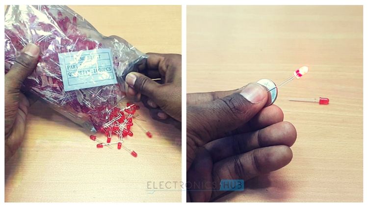
Testing the LEDs
As I’ve already mentioned earlier, we need 512 LEDs. The first step is to test all the 512 LEDs. You can use a 3V Lithium Cell to test the individual LED. This step is very important because once you begin soldering the LEDs, it will be difficult to remove them.
Building the Layers
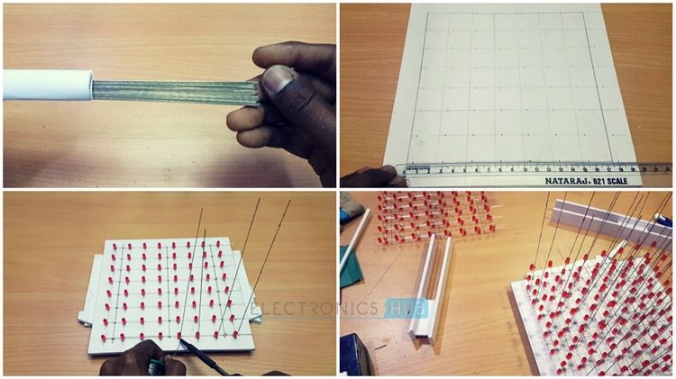
Next step is to create the layers. Each layer is made up of 8×8 LED Matrix consisting of 64 LEDs. In order to build the layers, take a Sunboard and make holes at a distance of 2.5CM. Place the LEDs and start soldering all the cathodes together.
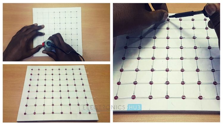
In order to increase the strength of the layer, solder few connecting wires between LEDs. In addition to acting as support bars, these wires will also short all the cathodes of that particular layer.
Now, test the LEDs once again as replacing a faulty LED will be somewhat easy at this stage. Once everything is done, put aside the completed layer and continue making seven other layers.
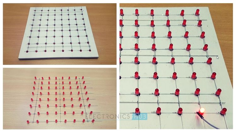
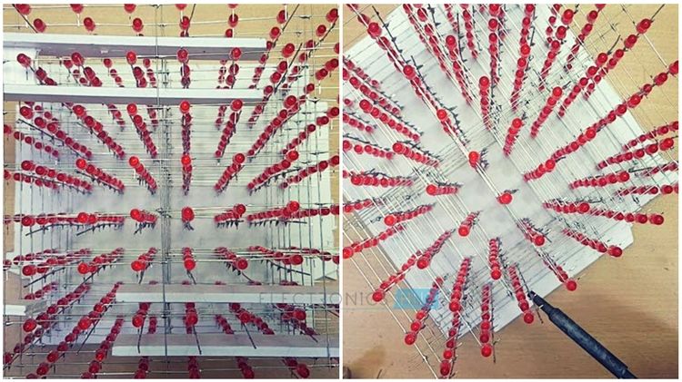
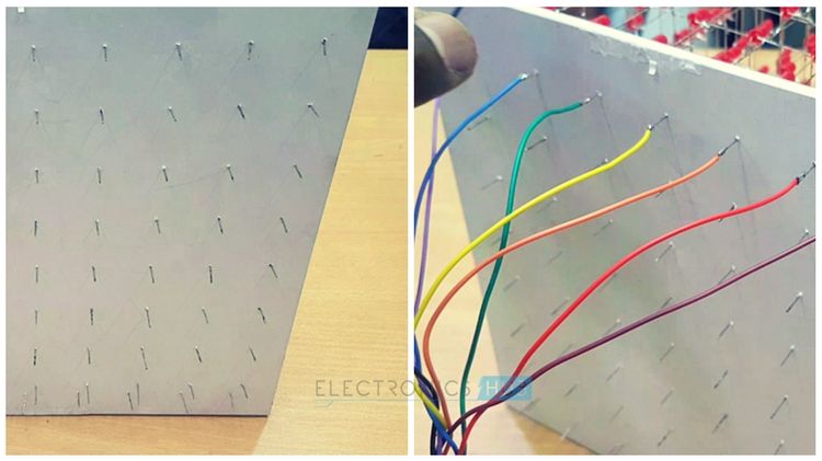
Stacking up Vertical Layers
After completing eight layers, we will now proceed with stacking those layers vertically. Take a Sunboard and mark 64 holes to insert poles for 64 Anode Terminals. Start soldering layer by layer and use any object like a ruler or even a piece of Sunboard (of width roughly 2.5CM) to separate the layers.
Finished structure after stacking all the eight layers, will look something like this.
The 64 Anode poles must protrude out of the Sunboard at the bottom in order solder wires for connection. After soldering all the 8 layers with the Anode Poles, solder wires to the Anode poles. This completes the actual Cube part of the 8x8x8 LED Cube.
Next, we will continue to design the main circuit board for housing all the ICs, transistors and the Arduino Nano board.
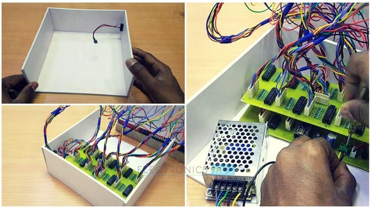
Designing the PCB
We have designed two PCBs for this Project: one for all the eight 74HC574 IC’s that get connected to the Anode rows of the LED cube and the other board for Arduino Nano, transistors and power supply components.
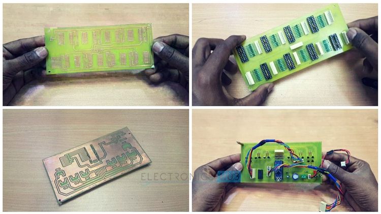
Fix the boards using standoffs and connect the LED Cube to the PCBs using ribbon cables at their appropriate places.
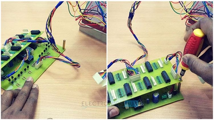
Housing for PCBs and Power Supply
Using Sunboard, make a housing for the PCBs and the Power Supply. This piece also acts as a base for the LED Cube. Insert the PCBs into the housing and connect the power supply through a switch.
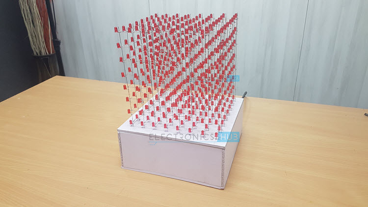
Final Build
The final build of the 8x8x8 LED Cube is shown in the image below. The structure is very strong and all the electronics including the power supply are concealed inside the base.
Circuit Diagram
The following image shows the complete circuit diagram of the 8x8x8 LED Cube using Arduino Nano.
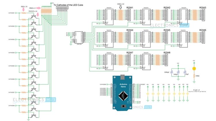
NOTE: The above image might not be very clear due to extreme compression. If you want a clearer circuit diagram, you can download it from this link.
Code
The code is developed based on the work of “chr” from Instructables. There are many codes available in the internet that you can use.
Final Word
As I said in the beginning of the article, building an 8x8x8 LED Cube is every electronics hobbyist’s dream and we are no exception to that. So, after postponing the LED Cube project for a long time, we have finally finished it.
It took nearly 24 working hours to build the 8x8x8 LED Cube (testing LEDs, bending and cutting the LEDs, making 8 LED Layers each consisting of 64 LEDs, straightening wire for adding tensile strength, stacking those layers vertically, designing PCB, etching PCB, soldering components on the PCB, connecting LED Cube to the PCB, dumping the code and testing the output).
If you have made a similar project (even a smaller one like 4x4x4 LED Cube), congratulations to you. It shows your dedication, effort and patience in building a project.

24 Responses
Nice, but way too difficult. I got a Arduino Uno and I would like to build something like the above, but with much less diodes, e. g. 16 diodes. Further I want to program by myself. Any suggestions?
Thank you for sharing your work.
It is good to see another description on how to build this cube.
The RED version is so cute.
PS: It is always good to link to your source / inspiration.
Thank you.
please the PCBs and the circuit diagram are not really understandable can you explain how to connect the capacitors and if you can send me pictures of the PCBs to my email
a.josef95@yahoo.com thanks
I also don’t really get how the capacitors are connected etc like the comment above me, can you explain it to me at: timlanders93@hotmail.com thanks.
There are 9 ICs in the circuit (8 are 74HC574 Octal D Flip-flop ICs and one is 74HC138 3-to-8 Demultiplexer). All these ICs have corresponding VCC and GND Pins. You should connect 0.1µF Capacitor across these terminals of individual ICs. So, a total of nine 0.1µF capacitors are required.
Can you please post the source code?
Sir can u give me pcb design plzz
CAN YOU MAIL ME PCB DESIGN OF 1 LAYER PLEASE. I MADE 4x4x4 ON MY OWN.now i am going ahead for 8x8x8
codes please ???????????????
Sir,
This is a very beautiful design.
Thank you for this.
Sorry for my English, I am 74 years Flemish speaking in Belgium and have never learned English.
This I would certainly make during this coming winter.
Can I please get the code?
I myself can not make such code unfortunately. Such a thing should I study to really made codes. My email: p.vanovermeire@gmail.com
Thank you for the response.
As I mentioned in the post, “chr” from Instructables inspired us to implement the project. I have used the same code from here – https://www.instructables.com/id/Led-Cube-8x8x8/
You can download the code from “Step 70” in the instructable.
(I am not providing the code in this post for obvious reasons. Hope you understand.)
Sorry Ravi,
You have the code written in something that I don’t know: avrdude-c usbtiny.
That would be so for installation a xxx. ino. It is this that I would like to,
The other are listed and I have found such as: arduinocube. ledcube_8x8x8. cube_pc-v pde-0.1. tar-hex-ledcube_8x8x8_eeprom. eep-ledcube_8x8x8-v 0.1.2. tar – test. hex
The other meaning EAGLE files
But no xxx.ino
To write them, this is going a little too far for me. May upload on Atmega 32 using Arduino Uno Board, but otherwise???
In “Step 70” of the afore mentioned instructable, there is a file called “arduinocube.pde” available for download. Download that file and change the extension to .ino.
Thanks, for the very fast reply
Dear Mr. Ravi,
First, congrats for the project. You did a very aligned eds and cleaned job. This has a professional aspect.
I have one question: are you able to sell the PCBs? Or sell me the project file to produce in my country? Please let me know. I’m thanking you in advance,
Good wishes
Paulo Arruda
Can i make it using Ardiuno UNO ?
Yes.
How can I make it using ardiuno uno ?
Ravi ji I am very much thankful to u to share us this beautiful project and I am going to make it soon. Just want know that what did u do with DE to DO and OE pin and second please share your both PCB design with high resolution so that I get more strength with this project.
Hello Ravi,
Have one final question.
Where or to what are the 0.1 µ f connected?
Is that to the VVC and the GND of the 74HC136 and 74H574?
Yes. They are the decoupling capacitors (between VCC and GND).
Circuit diagram is not clear please send me it’s design kirtidhawan4444@gmail.com
Were connect 10k ohm resistor short link 5v supply in your circuit diagram