For analyzing DC circuits , generally we use different methods such as ohm’s law, network theorems and other circuit simplification tools. A DC circuit analysis is performed mainly to determine the unknown quantities such as voltage, current, resistance and power which are allied with one or more elements of an electronic circuit. As a basic law for simplifying the circuits, Ohm’s law defines a linear relationship between voltage, current and resistance. Let us know in detail about this ohm’s law.
Ohm’s Law
Ohm’s Law is a fundamental principle in electricity that describes the relationship between voltage, current, and resistance in an electrical circuit. It states that the current flowing through a conductor between two points is directly proportional to the voltage across the two points and inversely proportional to the resistance between them.
The Ohm’s law is usually expressed with the formula I = V / R
In algebraic form, V∝ I
V = IR
Where
I is the current flowing through the circuit and it is measured in Amps
V is the voltage applied across the circuit and it is measured in Volts
And R is the proportionality constant, called as Resistance which is measured in Ohms.
This resistance is also specified in kilo Ohms, Mega Ohms, etc.
Therefore, ohm’s law tells that current flow in circuit is directly proportional to the voltage and is inversely proportional to the resistance in that circuit. Ohm’s law can be applied to the individual parts or to an entire circuit.
Mathematically, Current, I = V/R
Voltage, V = IR
Resistance, R = V/I
Ohm’s Law Triangle
Below arrangement shows that relation between different quantities in ohm’s law, is referred as ohms law triangle. This is a simple method of describing and also easy to remember the relation between the voltage, current and resistance.
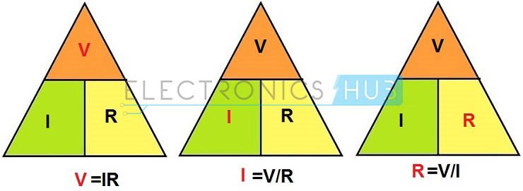
Above figure shows the ohm’s law triangle where individual terms like voltage, current and resistance and their formulas are represented from basic ohms law equation. In the above figure, one parameter is calculated, from the remaining two parameters. Thus it can be concluded that, when the resistance is high, the current flow will be low and current flow is high, when resistance is low for any applied voltage.
Electric Power
The electric power gives the rate at which energy is transferred by a circuit. Electric power is measured in watts. This power is consumed when a voltage causes current to flow in circuit.
Therefore , the electric power is the product of voltage and current.
Mathematically, P = VI
From ohms law, V = IR and I = V/R
Substituting in the power equation
P = I2 R
P = V2/ R
Therefore, Electric power, P =VI or I2 R or V2/ R
These are the three basic formulas to find the electric power in a circuit. Thus power can be calculated when any of the two quantities are known.
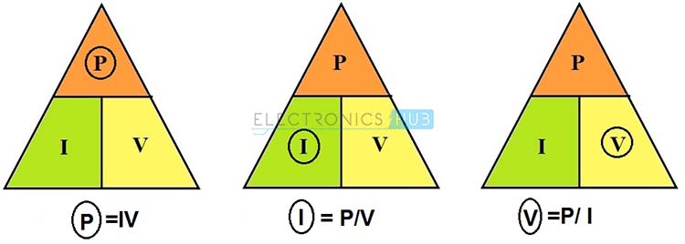
Power Triangle
Similar to the ohms law triangle, below figure shows the power triangle to give the relation between the power, voltage and current. Individual parameter equations are easily remembered by this figure. Round off and hide the parameter which is to be measured and the remaining two parameters position gives the equation to find the hided or rounded parameter as shown in below figure.
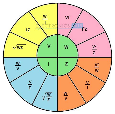
Ohm’s Law Pie Chart
Preceding to the above two concepts, there is another method for finding circuit parameters using ohm’s law that is Ohm’s law pie chart. By using the ohm’s law pie chart one can easily remember all the equations to find voltage, current, resistance and power which are necessary to simplify the electric circuits that can be simple or complex.
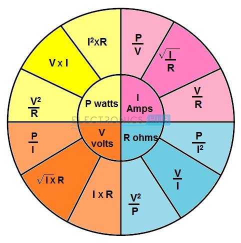
Above figure shows pie chart that gives a relationship between power, voltage, current and resistance. This chart is divided into four units for power, voltage, resistance and current. Each unit consists of three formulas with two known values for each formula. From the chart, for finding each parameter in a circuit, we can use any one from available three formulas.
Graphical Representation of Ohm’s Law
For a better understanding of this concept, experimental set up is given below where an adjustable voltage source with six cells (2V each) is connected to the load resistor through a voltage selector switch. Measuring instruments like voltmeter and ammeter are also connected to the circuit to measure the voltage and current in the circuit.
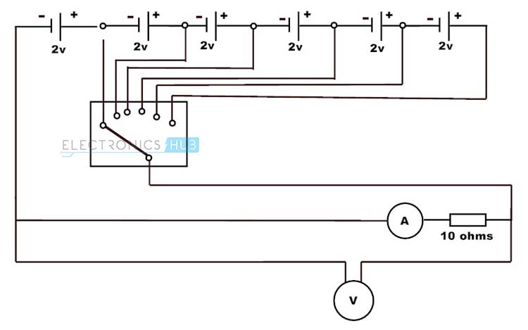
First connect the 10 ohms resistor and place the selector switch at position one. Then the ammeter reads 0.2A and voltmeter reads 2V because I = V/R , i.e. I = 2/10 = 0.2A. Next change the selector switch position to second cell, to apply the 4V across the load and note down the ammeter reading. As the selector changes stepwise from first position to the last we will get the current values like 0.2, 0.4, 0.6, 0.8, 1, 1.2 for voltages values of 2, 4, 6, 8, 10 and 12 respectively.
Similarly place the 20 ohms resistor in place of 10 ohms resistor and do the same procedure as above. We will get the values of current 0.1, 0.2, 0.3, 0.4, 0.5, 0.6 for the voltage values of 2, 4, 6, 8, 10 and 12V respectively. Plot the graph of these values as shown below.
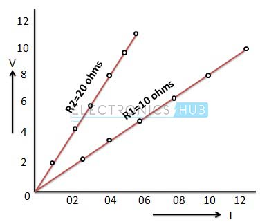
In the above graph, for a given voltage, the current is smaller when the resistance is greater. Consider the case of voltage 12V applied where current value is 1.2A if the resistance is 10 ohms and it is 0.6 ohms, when the resistance is 20 ohms. Similarly for same current flow, the voltage is greater as the resistance is greater.From the above results, the ratio of voltage to current is constant when the resistance is constant. Therefore the relationship between the voltage and current is linear and the slope of this linear curve get steeper as the resistance is greater.
Example of Ohm’s law
Consider the below circuit where battery of 6V is connected to a 6 ohms load. Ammeter and voltmeters are connected to the circuit to measure the current and voltage practically. But using the ohm’s law we can find the current and power as follows.
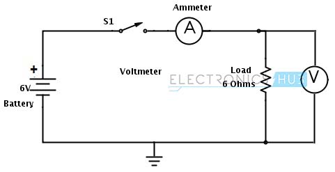
From ohm’s law
V = IR
I = V/R
I = 6/6
I = 1 ampere
Power, P = VI
P = 6×1
P = 6 watts
But practically the ammeter doesn’t show the exact value due to the internal resistance of the battery. By including the internal resistance of the battery (Assume battery has internal resistance of 1 ohm), the current value is calculated as follows.
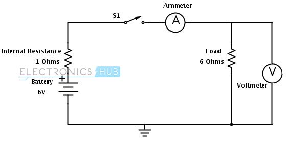
Total resistance of the circuit is 6 +1 = 7 ohms.
Current, I = V/R
I = 6/7
I = 0.85 Amps
Headlamps Circuit in a Car
The below figure shows the headlamps circuit in the motor car excluding the control circuitry. With the application of ohm’s law we can find out the current flowing through each light. Generally each light is connected in parallel to the battery, which allows other lights to glow even if anyone is damaged. A battery of 12 V is supplied to these parallel lamps where lamps have the resistance of 2.4 each (considered in this case).
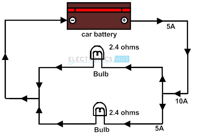
The total resistance of the circuit is R = R1x R2/ (R1 + R2) as they are in parallel.
R = 5.76/ 4.8 = 1.2
Then the current flowing through the circuit is I = V/R
I = 12/ 1.2
I = 10A.
Current flowing through individual lamp is I1 = I2 = 5 A (due to the same resistances)
Ohm’s Law for AC circuits
In general, ohm’s law can also be applied to AC circuits. If the load is inductive or capacitive, then reactance of the load is also considered. Therefore, with some modifications of ohms law by considering reactance effect, it can be applied to AC circuits. Due to the inductance and capacitance in AC, there will be a considerable phase angle between voltage and currents. And also the AC resistance is called impedance and is represented as Z.
Thus the ohms law for AC circuits is given as
E = IZ
I = E/Z
Z = E/I
Where E is the voltage in AC circuit
I is the current and
Z is the impedance.
All the parameters in the above equation are in complex form which includes the phase angle. Similar to the DC circuit pie chart, ohm’s law pie chart for AC circuit is given below.
Example of Ohm’s Law (AC Circuits)
Consider the below circuit where AC load (combination of resistive and inductive) is connected across the AC supply of 10V, 60Hz. The load has resistance value of 5 ohms and an inductance of 10mH.
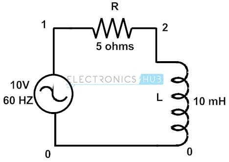
Then the impedance value of the load , Z = R + jXL
Z = 5 + j (2∏×f × L)
Z = 5+ j (2×3.14× 60×10× 10-3)
Z = 5 + j3.76 ohms or 6.26 ohms at a phase angle of -37.016
The current flowing through the circuit is
I = V/Z
= 10/ (5+ j3.76)
= 1.597A at a phase angle of -37.016
