Many practical circuits contain a combination of resistive, inductive and capacitive elements. These elements cause the phase shift between the parameters of electrical supply such as voltage and current.
Due to the behavior of voltage and currents, especially when subjected to these components, power quantity comes in different forms.
In AC circuits, voltage and current amplitudes will change continuously over a time. Since the power is the voltage times the current, it will be maximized when currents and voltages are lined up with each other.
This means that zero and maximum points on current and voltage waveforms occurs at the same time. This can be referred as the useful power.
In case of an inductor or capacitor elements there exists 900 phase shift between the voltage and current. So, the power will have a zero value every time when either voltage or current has zero value.
This is not a desirable condition because no work is being performed at the load even though source is generating power. This power is called reactive power. Let us discuss these forms of power in electrical AC circuits in brief.
Power in AC Circuits
The power in any electrical circuit can be obtained by performing multiplication of voltage and current values in that circuit. This is applicable for both DC and AC circuits.
i.e., power = (Current value) x (Voltage value)
P = V x I
Power is measured in watts. In DC circuits and pure AC circuits without any non linear components, the current and voltage waveforms are ‘in phase’.
So the power at any instant of time in that circuit is obtained by multiplying the voltage and current. However, in case of AC circuits, this will not be so (as mentioned above the existence of phase shift).
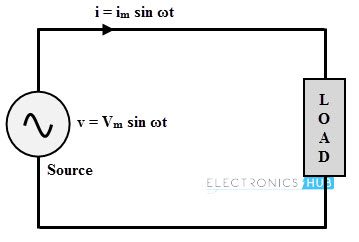
Consider the above circuit in which AC supply is given to a load.Voltages and currents in the circuit are given as
v = Vm sin ωt ⇒ v = √2 V sin ωt
i = Im sin ωt ⇒ i = √2 I sin (ωt ± ϕ)
Where V (= Vm/√2) and I (= Im/√2) are the RMS values of applied voltage and current flowing through the circuit respectively. Φ is the phase difference between voltage and current, to which + sign indicates the leading phase angle while negative indicates the lagging phase angle.
Then the instantaneous power delivered to load by source is given by,
p = vi = 2 VI sin wt sin (ωt ± ϕ)
= VI (cos ϕ – cos (2ωt ± ϕ)
p = VI cos ϕ (1 – cos 2wt) ± VI sin ϕ sin2wt
The above power equation consists of two terms, namely
- A term proportional to VI cos ϕ which is pulsating around the average value of VI cos ϕ
- A term proportional to VI sin ϕ pulsating at twice the supply frequency, producing an average of zero over a cycle.
So there are 3 forms of powers in AC circuits. They are
- Active power or True power or Real power
- Reactive power
- Apparent power
Active Power
The actual amount of power being dissipated or performs the useful work in the circuit is called as active or true or real power. It is measured in watts, practically measured in KW (kilowatts) and MW (megawatts) in power systems.
It is denoted by the letter P (capital) and it is equal to the average value of p = VI cos ϕ. It is the desired outcome of an electrical system which drives the circuit or load.
P = VI cos ϕ
Reactive Power
The average value of the second term in the above derived expression is zero, so the power contributed by this term is zero. The component, which is proportional to VI sin ϕ is called as reactive power, represented by the letter Q.
Even though it is a power, but not measured in watts as it is a non active power and hence, it is measured in Volt-Amperes- Reactive (VAR). The value of this reactive power can be negative or positive depends on the load power factor.
This is because inductive load consumes the reactive power while capacitive load generates the reactive power.
Q = VI sin ϕ
Significance of Reactive Power
The reactive power is one of the total power components that travel back and forth in the circuit or line. It can be termed as the rate of change of energy with respect to time that keeps on flowing from source to reactive components during positive half cycle and back to the components from source during negative cycle. Therefore, it never gets consumed by the load.
In the normal sense, this fictitious power is not at all a power but only a power-like measure of reactive component of the current. If there exist excess amount of reactive power, power factor is greatly reduced. This low power factor is undesirable in terms of operating efficiency and operational costs.
And also this power causes to draw additional current from the supply leads to additional losses and greater capacity of the equipments. That’s why this power has been referred as the cholesterol of power lines in a joking manner.
In order to minimize losses and to increase the capacity of the available equipment, utility companies make use VAR compensation techniques or power factor correction equipments. Generally, these reactive compensation techniques are implemented at the load side.
However, this reactive power is useful for generating necessary magnetic fields for operation of inductive devices like transformers, AC motors, etc. It also helps to regulate the voltage in heavy power supply mechanisms.
Apparent Power
The complex combination of true or active power and reactive power is called apparent power. Without reference to any phase angle, the product of voltage and current gives the apparent power. The apparent power is useful for rating the power equipment.
It can also be expressed as the square of the current multiplied by the circuit’s impedance. It is denoted by the letter S and measured in Volt-Amperes (VA), practical units include KVA (Kilo volt-amperes) and MVA (mega volt-amperes).
Apparent power = RMS voltage × RMS current
Apparent power, S = V × I
In complex form, S = V I*
S = V ∠00 I ∠ ϕ (for lagging load current)
S = V I ∠ ϕ
S = V I cos ϕ + jV I sin ϕ
S = P + jQ
Or S = I2Z
Power Triangle
The relation between active, reactive and apparent power can be expressed by representing quantities as vectors, which is also called as power triangle method as shown below. In this phasor diagram voltage is considered as reference vector. The voltage & current phasor diagram is the basis for the formation of the power triangle.
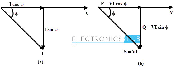
In figure (a), current lags the applied voltage by angle ϕ. The horizontal component of the current is I cos ϕ and the vertical component of the current is I sin ϕ. If each of the current phasor is multiplied by the voltage V, the power triangle is obtained as shown in the figure (b).
The active power is contributed by the component I cos ϕ in phase with voltage while reactive power is produced by the quadrature component.
Therefore, the apparent power or the hypotenuse of the triangle is obtained by combining real and reactive power vectorially.
Using Pythagoras’s theorem, the sum of squares of the two adjacent sides (active power and reactive power) is equal to the square of the diagonal (apparent power). i.e.,
(Apparent power)2= (Real Power)2
S2 = P2+ Q2
S = √((Q2 + P2))
Where
S = apparent power measured in kilovolt amps, kVA
Q = reactive power measured in kilovolt amps reactive, kVAR
P = active power measured in kilowatts, kW
In terms of resistive, inductive and impedance elements, the power forms can be expressed as
Active power = P = I2R
Reactive power = Q = I2X
Apparent power = S = I2Z
Where
X is inductance
Z is impedance.
Power Factor
The power factor is the cosine angle between the voltage and current. The power factor can be expressed in terms of the above discussed power forms. Consider the power triangle in above figure in which power factor is the ratio of active power to apparent power. Power factor defines the efficiency of the circuit.
Power factor (PF) = (Active power in watts)/(Apparent power in volt amps)
PF = VI cos ϕ / VI
PF = cos ϕ
Example Problem
If an AC power supply of 100V, 50Hz is connected across a load of impedance, 20 + j15 Ohms. Then calculate the current flowing through the circuit, active power, apparent power, reactive power and power factor.
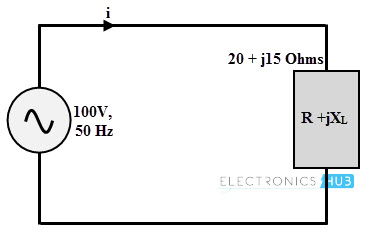
Given that, Z = R + jXL = 20 + j 15 Ω
Converting the impedance to polar form, we get
Z = 25 ∠36.87 Ω
Current flowing through the circuit,
I = V/Z = 100∠00 /25 ∠36.87
I = 4 ∠–36.87
Active power, P = I2R = 42 × 20 = 320 watts
Or P = VI cos ϕ = 100 × 4 × cos (36.87) = 320.04 ≈ 320 W
Apparent power, S = VI = 100 × 4 = 400 VA
Reactive power, Q = √ (S2 – P2)
= √ (4002 – 3202) = 240 VAr
Power factor, PF = cos ϕ = cos 36.87 = 0.80 lagging.
