This circuit is low cost and can be constructed easily. By using this circuit, we can control any house hold appliance with the help of remote. In this project, there are two parts – one is in transmitting section and the other is in receiving section. Receiving section will be in a stable position which is connected to any load and transmitter will act as a normal remote.
Do you know – How RF Remote Control Circuit Works for Home Appliances?
Outline
ToggleBlock Diagram of Infrared Remote Control Switch:
IR Remote Control Switch Diagram Explanation:
- The main function of this remote control switch is to control any load (TV, Radio, Stereo, Fan, Light, etc.). In this circuit, we are using one switch for operating the transmitter, with this we can switch on or off the TV, motor, radio or any other home appliances.
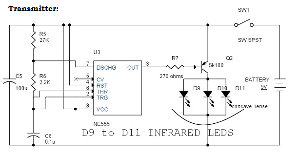
- We can even control the volume of TV, radio and many more by adding extra circuitry to the actual circuit. Here in the transmitter section, we have NE555 timer which is configured in astable mode and infrared LEDs whose infrared rays are directed by the concave lens and the source of power is from 9V battery.
- Switch in the circuit plays the key role in the transmitter circuit. When the switch is closed, the power from the battery turns on the NE555 timer which will act as an astable multivibrator. The infrared LEDs which are connected to the output of NE555 will get high and produce the infrared beam through the concave lens.
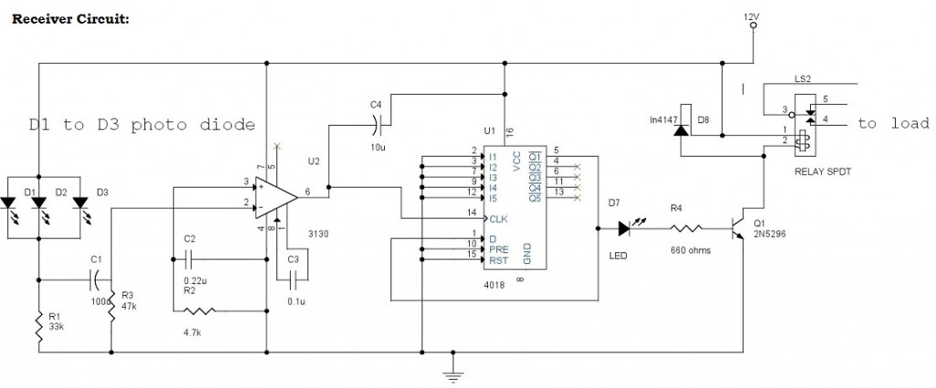
- When the infrared beam from the transmitter is reached by the receiver section, the photo LEDs will receive the infrared beam and charge the capacitor which will increase the input voltage of one pin of operational amplifier and high output is generated. This high output is given to the 4018 Counter as input and counter will drive the load through a relay to switch on or switch off accordingly.
Infrared Remote Control Switch Circuit Components:
CA3130: CA3130 is a BiCMOS operational amplifier, which has very high input impedance, very low input current and high speed performance. It had very low input swing i.e. below 0.5V; the operating supply voltage is of around 5V to 16V. It will permit the output swing also. Maximum differential voltage between two inputs should be 8V. The main applications are they are used as single supply amplifiers, timers or monostable multivibrators, voltage followers and detectors, peak detectors etc. They can also be used in photodiode – a sensor amplifier that’s why we use this component in our circuit as amplifier.
CD4018: The main function of counter is to store (and sometimes displays) the number of times a particular event or process has occurred, often in relationship to a clock signal. CD4018 is the 16 pin counter in which there are 5 jam inputs (sets the counter to that number and sends the number out immediately. If the number is outside the minimum and maximum count range, this message is ignored), clock, data, preset, enable and reset pins. It had around 5 Johnson counter (twisted ring counter) in which output of the last stage is inverted back and given as input to the first stage. The main features are fully static operations, different noise margins at different voltages (1V noise margin is 5V), supply voltage ranges from 3V to 18V. Clock input frequency also varies at different supply voltage. 5V VDD will give around 3Mhz frequency. Counters are used in different applications like frequency division, counter control, programmable decade counter, minicomputer, etc.
Circuit Diagram of Infrared Remote Control Switch:
Circuit Explanation:
- In the receiver section there are 3 photodiodes which will detect the infrared signals from the receiver and produce leakage current to the capacitor C1. This current is given to the inverting input of 3130 IC which will get triggered by this current and give amplified output. Remaining all other pins are connected to the ground.
- R2 and C2 are used to stop the unwanted signals from triggering the IC. C3 is used for high gain which is used as comparator amplifier.
- The output of IC3130 is given to the pin14 CLK of Johnson counter 4018. The output of 4018 IC will go high by applying successive clock pulses.
- The resistor R4 is used to stop loading the transistor. The transistor will get ON when the output of 4018 is high and drive the relay to operate in 12V. The diode D4 will protect the relay from reverse current.
- The relay will switch ON or OFF the appliance that is connected to it. LED will act as a visual indicator and also stops the reverse voltage which will effect the counter.
- In the transmitter section, the 555 timer is configured in astable mode and resistors R5, R6 and capacitor C6 are adjusted to give the 5Khz operating frequency.
- When the switch is ON, the capacitor C6 will get charged and when the switch is OFF, it will be discharged through R6 and 555 timer internal transistors. When switch on the 555 timer, output pin3 will be high this will trigger the transistor SK100.
- Resistor R7 is used to stop loading of transistor. When transistor is ON, the infrared diodes which are connected to it will produce high intensity invisible infrared beam which should be given to the photo diodes of receiver.
Note:
- Operating voltage can be between 6V to 15V.
- Relay voltage rating should be equal to the main power supply.
- Heat sink can be attached to the transistor SK100 for compensating the heat dissipation.
- Concave lens is used for producing the strong rays of high intensity.
- The disadvantage in the circuit is switching time between the transmitter and receiver (if we produce the signal from transmitter, again we have to produce the signal after 5 to 6 seconds). Rapid switching like regular remote cannot be done.
Applications of Infrared Remote Control Switch:
- This circuit can be used for switch ON or OFF the TV, radio, washing machine and any electronic appliances.
- By using the relative relays, we can even switch ON or switch OFF the motor appliances also.


15 Responses
I want make 12 chi remote oprated relay
nice site…really good job….
Good
pls tell how much distance it would work ,i require approx 60 feet
pls tell how much distance it would work ,i require approx 60 to 70 feet
if you get that CD4018 on market it is necessary or need to be programmed before use it.
No need of Programming
SK 100 is not available.what should be the replacement for it???
SK100 is not available in market .what should be the replacement??
what will be the model no of D1 to D3?
mimi project
i am first project in eee
so some circuit in confus
so please easy under stading diagram in IR Remote Control Switch
thank u….very usefull
It’s good
I mad remote control moter giv me idea
Thanks for the blog loaded with so many information. Stopping by your blog helped me to get what I was looking for.