We have already studied how to control the home appliances using RF communication in the post RF Remote Control Circuit for Home Appliances. Now let us see how to design FM remote encoder and decoder circuit using RF600E and RF600D ICs. This pair of encoder and decoder ICs establishes the communication with high level security. The operating voltage of these ICs is from 2V to 6.6V DC.
This system uses FM (Frequency Modulation) for transmission. If you press any push button then corresponding code is generated at transmission section. Here encoder is used to convert parallel data to serial. This serial data is given to the FM Tx module to transmit. FM Rx module receives this serial data and fed to the decoder to produce the corresponding output.
FM Remote Encoder and Decoder Circuit Diagram:
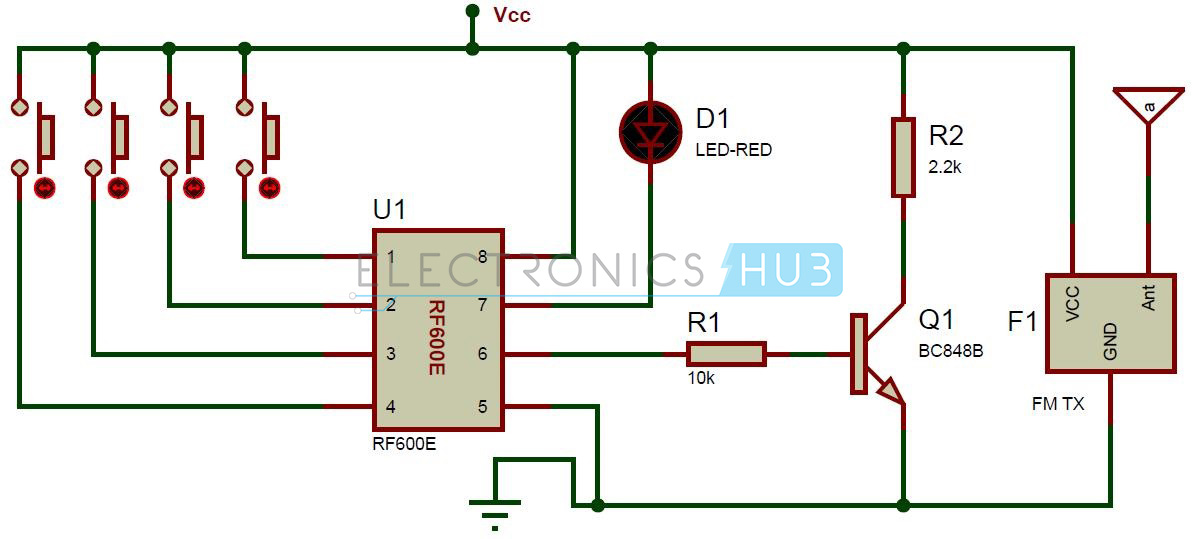
Transmitter Section:
Circuit Components:
- RF600E encoder
- FM Transmitter module
- 4 push buttons
- Bc848 Transistor
- Led
- Resistors – 2.2k, 10k
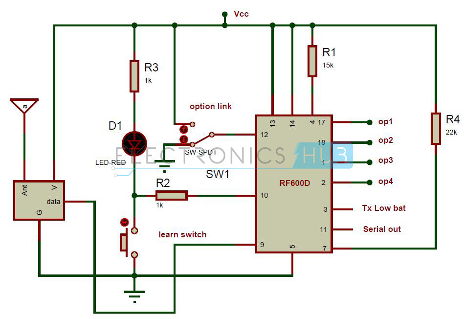
Receiver Section:
Circuit Components:
- RF600D Decoder
- FM Receiver module
- Slide switch
- Push button
- Red LED
- Resistors – 1k(2), 15k, 22k
FM Remote Encoder/Decoder Circuit Design:
The circuit mainly consists of two sections, one is Transmitter section used t transmit the remote data and other is Receiver section used to receive the data.
Transmitter Section:
This section consists of RF600E encoder, FM transmitter module, four switches and LED. Four push buttons are used to generate the parallel data. If you press any push button, then corresponding code is generated at the 6th pin of encoder. Here the LED which is connected to the 7th pin of encoder is used for indicating the signal transmission.
RF600E Encoder:
This pair of encoder and decoder ICs uses balanced Manchestar encoded data protocol for transmission. This encoder IC requires just fewer components to use it as a transmitter. The transmission is automatic there is no need of human intervention.
The data format includes a pre-amble, header, encrypted data followed by CRC bit. Here the packet size is 67 bits.
Low Battery Indication:
This encoder IC reads the battery status for each operation. If the voltage is below 3.8 volts then flag bit is transmitted to the decoder IC.
Pin Configuration:
Receiver Section:
The receiver section consists of RF600D decoder and its associated components. Pins 17, 18, 1 and 2 are the digital output pins corresponding to the input switches. If you press any push button, then the corresponding pin at decoder becomes low. Here SPDT switch is used to select latching or memory digital function. The learn switch is used to enter the decoder IC into the “learn mode”.
RF600D Decoder:
In this RF chipset, protocol data is sent serially as a stream of ASCII characters with a baud rate of 9600 bits per second. While coming to the frame format 8 data bits with one stop bit.
Pin Configuration:
How to Operate FM Remote Encoder and Decoder Circuit?
- Give the connections as per the circuit diagram.
- Connect the LED’s at the decoder outputs.
- Apply 5V supply to the both transmitter and receiver sections.
- Initially all the LED’s will glow.
- Now press the first button at transmitter section, you can observe that first LED will off at decoder section. In the same way for each switch at transmitter the corresponding LED at receiver will off.
- Switch off the power supply for both transmitter and receiver sections.
FM Remote Encoder/Decoder Circuit Advantages:
- Stand alone operation
- LED indication of signal transmission
- Battery low indication
- Manchester modulation
- Sleep mode.
FM Remote Encoder/Decoder Circuit Applications:
- Used in general purpose Remote control applications
- Used in burglar alarm systems
- used in automotive systems
- Used in Electronic door locks
Circuit Limitation:
- This circuit is theoretical and may require some practical changes.

6 Responses
Sir i want make wirless remot control 6or7 switch on off .i want make with my hand so plz help me
RF600D and RF600E can works for separately?
hello sir
how to transmit audio signals using FM module
Hello sir,
Can we use FM module?
If yes, then how to use it.
How far can the Recever and Transmitter be connected?
This remote control is what I need.
What is the domain of the project.
What are the components used?