In this session we will see how to interface 16×2 LCD to PIC18F4550 microcontroller which is of family PIC18F. You can get information of 16×2 LCD in the session How to Interface 16X2 LCD with 8051 Microcontroller.
Features of PIC18F4550:
- PIC18F4550 belongs to the PIC18F family; PIC18F4550 is an 8bit microcontroller and uses RISC architecture. PIC18F4550 has 40 pins in PDIP (dual in line package) and 44 pin in TQFP (Quad flat package).
- 32KB flash memory, 2048 bytes of SRAM (synchronous Random Access memory), EEPROM (Electrically Erasable Program Read Only Memory) of 256 bytes are embedded in the PIC18F4550.
- It has 35 I/O pins for interfacing and communication with other peripherals, 13channel of 10bit analog to digital converters which are used for interfacing and communicating the analog peripherals (DC motor, LDR, etc.).
- It has 2 CCP and 1 ECCP module that is enhanced capture and compare module which is mainly used for modulation and waveform generation functions. CCP module is of 16bit register works as 16 capture bit register, 16 compare bit register, and PWM and duty cycle register.
- PIC18F4550 has SPI (serial peripheral interface) and i2c (inter integrated circuit) for master and slave modes. It has SPP (Streaming Parallel Port) for USB streaming transfer.
- PIC18F4550 is embedded with 4 timer modules (timer0 to timer3), 2 comparator modules and 3 external interrupt. It has Dual Oscillator options allow microcontroller and USB module to run at different clock speeds. It can operate in 2.0V to 5.5V
16X2 LCD Interfacing PIC Microcontroller Circuit Diagram:
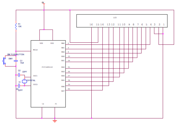
16X2 LCD Interfacing PIC Microcontroller – Circuit Explanation:
The resistor R1 is used for giving the contrast to the LCD. The crystal oscillator of 12 MHz is connected to the OSC1 and OSC2 pins of Pic microcontroller PIC18F4550 for system clock. The capacitor C2 and C3 will act filters to the crystal oscillator. You can use different ports or pins for interfacing the LCD before going to different ports please check the data sheet whether the pins for general purpose or they are special function pins.
Programming PIC for Interfacing 16X2 LCD:
Interfacing LCD to PIC is not different from interfacing to 8051. The basic concept and gist of the programming is almost same. Visit the following link for more information https://www.electronicshub.org/interfacing-16×2-lcd-8051/.
Only the pins, registers and architecture using for interfacing will be different. When we look at the program, functions like initialization, sending data to the LCD will be almost same.
In the pic programming also for initializing the LCD the R/W pin should be low for writing the data, Enable pins should be high and register select pin (RS) should be high for writing the data. For sending a command the RS should be low, R/W pin should be low and enable pin should be high.
Initializing the LCD function:
lcdcmd(0x38);//Configure the LCD in 8-bit mode,2 line and 5×7 font
lcdcmd(0x0C);// Display On and Cursor Off
lcdcmd(0x01);// Clear display screen
lcdcmd(0x06);// Increment cursor
lcdcmd(0x80);// Set cursor position to 1st line,1st column
Sending command to the LC:
- rs=0; Register select pin is low.
- rw=0; Read/write Pin is also for writing the command to the LCD.
- en=1;enable pin is high.
Sending data to the LCD:
- rs=1; Register select pin is high.
- rw=0; Read/write Pin is also for writing the command to the LCD.
- en=1; enable pin is high.
Steps for Programming:
- Install MPLAB in your system and create a new project, in selecting device and family select PIC18F family and add PIC18F4550 controller to your project.
- Select the compiler which you have installed and add the file to your project. After adding the file paste the code which is given below and run it. As it is a precompiled and tested program you will not find any errors.
- After compiling the program with no errors dump the program into your development board using PICKIT2 or PICKIT3 programmer/ debugger.
- If you are not using PICKIT then just compile the code and make the HEX file use this HEX file for programming the PIC microcontroller.
Program for Interfacing LCD to PIC18F4550:
#define rs LATA.F0
#define rw LATA.F1
#define en LATA.F2
//LCD Data pins
#define lcdport LATB
void lcd_init();
void lcdcmd(unsigned char);
void lcddata(unsigned char);
unsigned char data[20]=”hello world”;
unsigned int i=0;
void main(void)
{
TRISA=0; // Configure Port A as output port
LATA=0;
TRISB=0; // Configure Port B as output port
LATB=0;
lcd_init(); // LCD initialization
while(data[i]!=’\0′)
{
lcddata(data[i]); // Call lcddata function to send characters
// one by one from “data” array
i++;
Delay_ms(300);
}
}
void lcd_init()
{
lcdcmd(0x38);
lcdcmd (0x0C);
lcdcmd(0x01);
lcdcmd(0x06);
lcdcmd(0x80);
}
void lcdcmd(unsigned char cmdout)
{
lcdport=cmdout;
rs=0;
rw=0;
en=1;
Delay_ms(10);
en=0;
}
void lcddata(unsigned char dataout)
{
lcdport=dataout;
rs=1;
rw=0;
en=1;
Delay_ms(10);
en=0;
}

2 Responses
Its vry helpful….
Hey there,
I am using pic18f87j11 pic micro-controller. i need to interface LCD with the same. i used above posted code with some modification onto it but its not working properly. Can you please help in sorting out with this problem ??