In this project, we will discuss about ACS712 Current Sensor, how a Hall Effect based current sensor works and finally how to interface the ACS712 Current Sensor with Arduino.
Introduction
If you recall the previous Arduino project, I have discussed about measuring voltages greater than 5V with Arduino using a Voltage Sensor. In this project, we will learn about measuring current using a Current Sensor (ACS712 Current Sensor to be specific).
A Current Sensor is an important device in power calculation and management applications. It measures the current through a device or a circuit and generates an appropriate signal that is proportional to current measured. Usually, the output signal is an analog voltage.
Output Video
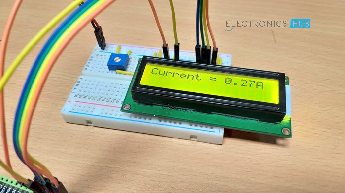
Take a look at the output video before proceeding further into ACS712 Current Sensor Module.
A Brief Note on ACS712 Current Sensor
The ACS712 Current Sensor is a product of Allegro MicroSystems that can be used for precise measurement of both AC and DC currents. This sensor is based on Hall Effect and the IC has an integrated Hall Effect device.
Coming to the output of the ACS712 Current Sensor, it produces an analog voltage that is proportional to AC or DC currents (whichever is being sensed).
The ACS712 IC is available in an 8-lead SOIC package and the following image shows its pin diagram.
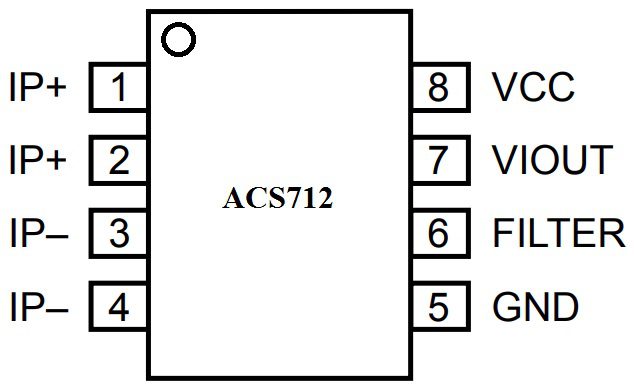
Let us now see the pin description of ACS712. The following table shows the pin number, name and description.
|
Pin Number |
Pin Name |
Pin Description |
|
1 & 2 |
IP+ |
+ve terminals for sensing current |
|
3 & 4 |
IP- |
-ve terminals for sensing current |
|
5 |
GND |
Signal Ground |
|
6 |
FILTER |
External Capacitor (to set the bandwidth) |
|
7 |
VIOUT |
Analog Output |
|
8 |
VCC |
Power Supply |
There are three variants of ACS712 Sensor based on the range of its current sensing. The optimized ranges are +/-5A, +/-20A and +/-30A. depending on the variant, the output sensitivity also varies as follows:
|
ACS712 Model |
Optimized Current Range |
Output Sensitivity |
|
ACS712 ELC-05 |
+/- 5A |
185 mV/A |
|
ACS712 ELC-20 |
+/- 20A |
100 mV/A |
|
ACS712 ELC-30 |
+/- 30A |
66 mV/A |
How ACS712 Current Sensor Works?
As mentioned earlier, the ASC712 is based on Hall Effect. There is a copper strip connecting the IP+ and IP- pins internally. When some current flows through this copper conductor, a magnetic field is generated which is sensed by the Hall Effect sensor.
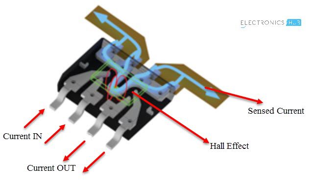
The Hall Effect sensor then converts this magnetic field into appropriate voltage. In this method, the input and the output are completely isolated.
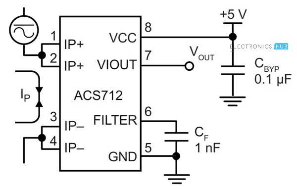
ASC712 Current Sensor Application Circuit
The typical application circuit using the ASC712 Current Sensor is given in its datasheet and the following images shows the same.
ACS712 Current Sensor Module
Using one of the variants of the ACS712 IC (5A, 20A or 30A), several manufacturers developed ASC712 Current Sensor Module boards that can be easily interfaced to a microcontroller like Arduino.
The following image shows the ASC712 Current Sensor board used in this project.
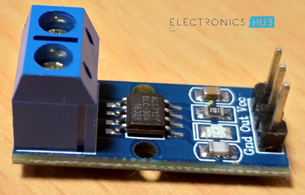
As you can see, it is fairly a simple board with only a few components including the ASC712 IC, few passive components and connectors.
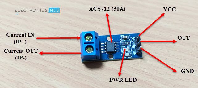
This particular board consists of ASC712 ELC-30 i.e. the range of this board is +/- 30A. the following image shows the components and pins on the board.
Interfacing ASC712 Current Sensor with Arduino
Measuring voltages (DC Voltages) with Arduino is very easy. If your requirement is to measure less than or equal to 5V, then you can directly measure using the Arduino Analog Pins. If you need to measure more than 5V, then you can use a simple voltage divider network or a voltage sensor module.
When it comes to measuring current, Arduino (or any other microcontroller) needs assistance from a dedicated Current Sensor. So, Interfacing an ACS712 Current Sensor with Arduino helps us in measuring current with the help of Arduino.
As ASC712 can be used for measuring either AC or DC currents, Arduino can be implemented to measure the same.
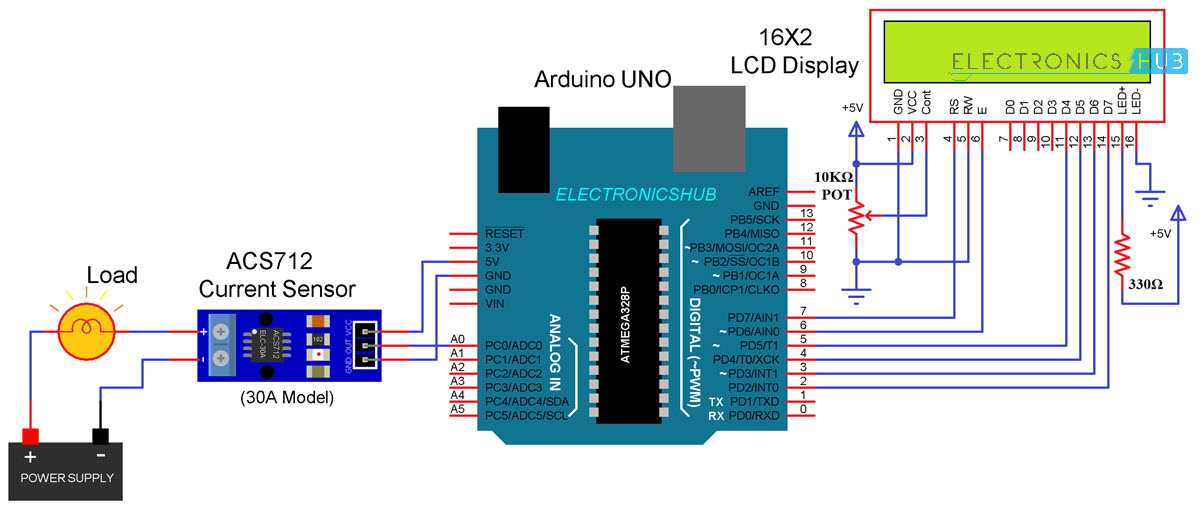
Circuit Diagram of ASC712 Current Sensor with Arduino
The circuit diagram of interfacing ACS712 Current Sensor with Arduino is shown in the following image.
Components Required
- Arduino UNO [Buy Here]
- ASC712 Current Sensor Module
- Load (like a lamp or a motor)
- Power supply (for load like battery)
- 16×2 LCD Display [Buy Here]
- 10KΩ Potentiometer
- 330Ω Resistor
- Connecting wires
Circuit Design
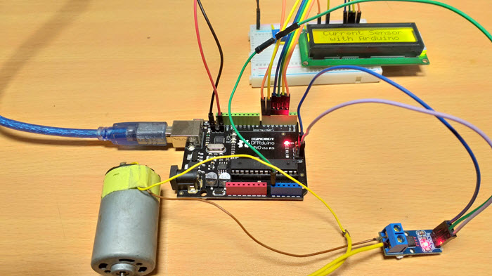
First, the load. I have used a 12V DC Motor along with a 12V power supply. The screw terminals of the ASC712 Current Sensor Module board are connected in series with the motor and power supply as shown in the circuit diagram.
Then connect the VCC, GND and OUT of the ASC712 board to +5V, GND and A0 of Arduino.
Now, in order to view the results, a 16×2 LCD is connected to Arduino. Its RS, E, D4-D7 pins are connected to Digital I/O Pins 7 through 2 of Arduino.
A 10KΩ POT is connected to Pin 3 of LCD and its VCC and GND are connected to +5V and GND.
Code
Working
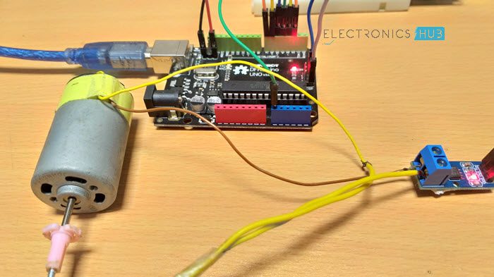
Make the connections and upload the code to Arduino. In the code, there is a small calculation for measuring the current.
First, assuming the VCC to ASC712 is 5V, when there is no current flowing through the IP+ and IP- terminals, the output voltage at VIOUT of ACS712 is 2.5V. This means that you need to subtract 2.5V from the voltage measured at the analog pin.
Now, in order to calculate the current, divide this value with the sensitivity of the sensor (185mV/A for 5A Sensor, 100mV/A for 20A Sensor and 66 mV/A for 30A Sensor).
The same is implemented in code as follows.
adcValue = analogRead(currentPin);
adcVoltage = (adcValue / 1024.0) * 5000;
currentValue = ((adcVoltage – offsetVoltage) / sensitivity);
Applications
The ACS712 Current Sensor can be used in various current measuring applications like:
- Inverters
- SMPS
- Battery Chargers
- Automotive Applications like Inverters, Power Steering etc.

9 Responses
This post was very helpful.Thanks to the team.
what is 5000
5000mV (Analog Reference Voltage – this is the default value).
boost type dc dc converter via arduino based sensors( acs712 + sensor voltage )
This is driving me nuts. Set up exactly as shown (except for different LCD display)
Have tried three different microprocessors, with input from pins A0 to A7 (and changed code appropriately).
Have tried two different ACS712 units. Have tried four different motors and an LED strip as loads.
Net result: No change whatsoever with load or load voltage. ADCvalue floats at random, absolutely no change with load whatsoever. Can I possibly have received TWO bad ACS712 boards?
there is correction in sentence “the sensitivity of the sensor (185mV/A for 5A Sensor, 100mV/A for 20A Sensor and 66 mV/A for 5A Sensor).” 66 mV/A for 30A …..
BTW fantastic explaination
Corrected.
Thank you.
Where is the offsetVoltage value from?
It is 2.5V (mentioned in the note)