In this tutorial, we will see how to test a Capacitor and find out whether the capacitor is working properly or it is a defective one. A Capacitor is an Electronics/Electrical component that stores energy in the form of Electric Charge. Capacitors are often used in electronics circuit boards or few electrical appliances and perform a variety of functions.
Also Check: LED Resistor Calculator
Why do we need to Test a Capacitor?
When a capacitor is placed in an active circuit (a circuit with active current flowing), charge starts to build up in the capacitor (on one of its plate) and once the plate of the capacitor can no longer accept any more charge, this means the capacitor is fully charged.
Now, if the circuit demands this charge (like a bypass capacitor, for example), the capacitor releases the charge back in to the circuit and it continues until the charge is completely released or the circuit stops demanding. These action are called as Charging and Discharging of Capacitor.
Basically, capacitors can be classified in to Electrolytic and Non – Electrolytic Capacitors. Like all electrical and electronics components, a capacitor is also sensitive to spikes and such voltage swings can damage the capacitors permanently.
Electrolytic Capacitor often fail due to discharging more current in a short period of time or cannot hold charge due to drying out over time. Non – Electrolytic Capacitors on the other hand fail due to leakages.
There are different methods to test whether a Capacitor is functioning properly or not. Let us see some of the methods to test a capacitor.
NOTE: Some of the methods mentioned here may not be the best ways to test a capacitor. But we included those methods just to specify the possibilities. Be very careful.
How to Discharge a Capacitor?
Before proceeding further and looking at different methods of testing a capacitor, let us understand how to properly discharge a capacitor. This is very important because capacitors can hold the charge even if the power supply is disconnected. If the capacitor is not discharged properly and if you accidently touch the leads of the capacitor, it will discharge through your body and cause an electric shock.
There are a couple of ways in which you can discharge a capacitor. There will be a dedicated tutorial on how to discharge a capacitor but for the time being, let us go through both these methods very briefly.
Using a Screwdriver
WARNING: This method is not preferred (especially if you are beginner) as there will be sparks generated while discharging, which might cause burns or other damage. Use this method as a last resort.
If the capacitor is in the circuit (on the PCB), then properly de-solder it and make sure not to touch the terminals of the capacitor. Now, take an insulated screwdriver (with a longer handle) and hold it in one hand. Take the capacitor in the other hand and touch the metal part of the screwdriver to both the terminals of the capacitor.
You will see sparks and hear some crackling sound as an indication of electric discharge. Repeat a couple of time to make sure that the capacitor is completely discharge.
Using a Discharge Resistor (Bleeder Resistor)
Now, we will see a safe way to discharge the capacitor. This method is often used in power supplies and other similar circuits where a Resistor, known as a Bleeder Resistor, is placed in parallel to the output capacitor so that when the power is turned off, the remaining charge in the capacitor is discharged through this resistor.
Take a large value resistor (usually, few kilo Ohms) with a high power rating (like 5W) and connect it across the terminals of the capacitor. Instead of directly connecting, you can make use of wires with crocodile clips on both the ends. The capacitor will slowly discharge and you can monitor the voltage across the terminals of the capacitor with a multimeter.
There is an easy to use “Capacitor Safety Discharge Calculator” from Digi-Key. Use this tool as a starting point.
For example, assume we have a 1000µF Capacitor rated for 50V and we want to discharge this capacitor down to 1V. Using a 1KΩ Resistor, it will take almost 4 seconds to discharge the capacitor. Also, the power rating of the resistor should be at least 2.5W.
NOTE: High Power Rated Resistors are usually expensive when compared to normal resistors (1/4 Watt or 1/2 Watt).
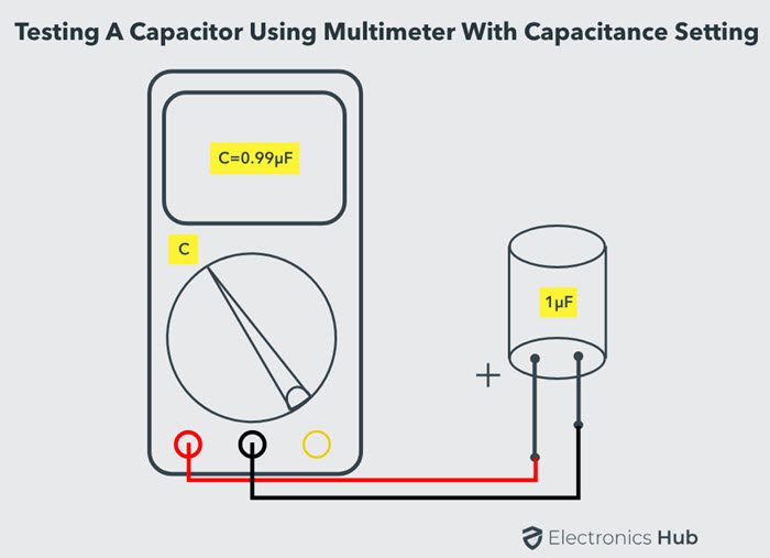
Method 1 Checking a Capacitor using Multimeter with Capacitance Setting
This is one of the easiest, quickest and accurate way to test a capacitor. For this, we need a Digital Multimeter with Capacitance Meter feature. Most of the mid and high end Digital Multimeters include this functionality.
The capacitance meter on the digital multimeters often display the capacitance of the Capacitor but few meters display other parameters like ESR, leakage, etc.
- In order to test a capacitor using Digital Multimeter with Capacitance Meter, the following steps can be followed.
- Disconnect the Capacitor from the circuit board and discharge it completely.
- If the capacitor ratings are visible on its body, make a note of it. Usually, the capacitance in Farads (often micro Farads) is printed on the body along with the voltage ratings.
- In the Digital Multimeter, set the knob for capacitance measurement.
- Connect the multimeter probes to the terminals of the capacitor. In case of a polarized capacitor, connect the red probe to the positive terminal of the capacitor (generally, the longer lead) and the black probe to the negative terminal (usually, there will be a marking on the side). In case of non – polarized capacitor, connect it either way as they do not have polarity.
- Now, check the readings on the Digital Multimeter. If the multimeter readings are closer to the actual values (mentioned on the capacitor), then the capacitor can be considered as a good capacitor.
- If the difference between the actual value and the measured reading is significantly large (or sometimes zero), then you should replace the capacitor as it is a dead one.
Using this method, capacitors ranging from few nano Farads to few hundreds of micro Farads of Capacitances can be measured.
Method 2 Checking a Capacitor using Multimeter without Capacitance Setting
Most of the low end and cheap Digital Multimeters do not include Capacitance Meter or Capacitance Settings. Even with these Multimeters, we can test a Capacitor.
- Remove the Capacitor from the circuit or board and make sure it is completely discharged.
- Set the Multimeter to measure resistance i.e., set the knob to Ohm or Resistance Settings. If there are multiple ranges of resistance measurement (on a manual multimeter), select a higher range (often 20 KΩ to 200 KΩ).
- Connect the multimeter probes to the leads of the capacitor (red to positive and black to negative in case of polarized capacitors).
- The Digital Multimeter will show a reading of resistance on the display and soon it will display the resistance of an open circuit (infinity). Note down the reading that was displayed for that short period.
- Disconnect the capacitor from the multimeter and repeat the test several times.
- Every attempt of the test should show similar result on the display for a good capacitor.
- If there is no change in the resistance in the further tests, the capacitor is dead.
This method of testing the capacitor might not be accurate but can differentiate between a good and bad capacitors. This method also doesn’t give the capacitance of the capacitor.

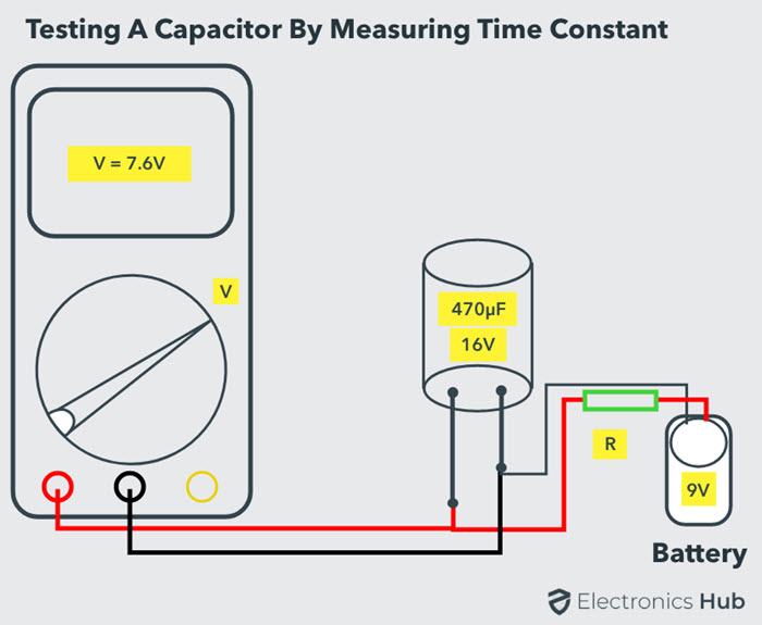
Method 3 Testing a Capacitor by measuring the Time Constant
This method is applicable only if the capacitance value is known and if we want to test whether a capacitor is good or dead. In this method, we measure the Time Constant of the Capacitor and derive the capacitance from the measured time. If the measured capacitance and the actual capacitance are similar, then the capacitor is a good one.
NOTE: An oscilloscope will be a better tool for this method than a multimeter.
Time Constant of a Capacitor is the time taken by a Capacitor to charge to 63.2% of the applied voltage when charged through a known resistor. If C is Capacitance, R is a known Resistor, then Time Constant TC (or Greek Alphabet Tau – τ) is given by τ = RC.
- First, make sure that the capacitor is disconnected from the board and is properly discharged.
- Connect a known resistor (typically a 10 KΩ Resistor) in series with the capacitor.
- Complete the circuit by connecting a power supply of known voltage.
- Turn on the power supply and measure the time taken for the capacitor to charge to 63.2% of the supply voltage. For example, if the supply voltage is 12V, then 63.2% of this is around 7.6V.
- From this Time and Resistance, measure the Capacitance and compare it with the value printed on the capacitor.
- If they are similar or nearly equal, the capacitor is functioning properly. If the difference is huge, we need to replace the capacitor.
The discharge time can also be calculated. In this case, the time take by the capacitor to discharge to 36.8% of the peak voltage can be measured.
Method 4 Test a Capacitor with a simple Voltmeter
All capacitors are rated with a maximum voltage that they can be applied with. For this method of testing a capacitor, we will use the voltage rating of a capacitor.
- Remove the capacitor from the board or circuit and properly discharge it. If you want, you can remove only one lead from the circuit.
- Look for the voltage rating on the capacitor. It will be usually mentioned as 16V, 25V, 50V etc. This is the maximum voltage which the capacitor can tolerate.
- Now, connect the leads of the capacitor to a power supply or a battery but the voltage should be less than the maximum rating. For example, on a capacitor with maximum voltage rating as 16V, you can use a 9V battery.
- If you have a bench power supply, then you can set a voltage which is less than the rated voltage of the capacitor.
- Charge the capacitor for a short period, say 4 – 5 seconds and disconnect the power supply.
- Set the Digital Multimeter to DC Voltmeter settings and measure the voltage across the capacitor. Connect the proper terminals of the voltmeter and capacitor.
- The initial voltage reading on the Multimeter should be close to the supplied voltage in a good capacitor. If the difference is large, then the capacitor is a faulty one.
Only the initial reading on the Multimeter must be taken in to account as the value will slowly fall down. This is normal.

Method 5 Test a Capacitor using Analog Multimeter (AVO Meter)
Analog Multimeters, like Digital Multimeters, can measure different quantities like Current (A), Voltage (V) and Resistance (O). In order to Test a Capacitor using Analog Multimeter, we are going to use its Ohmmeter functionality.
- As usual, disconnect the capacitor and discharge it. You can discharge a capacitor just by shorting the leads (very dangerous – be careful) but an easy way is to use a load like a high wattage resistor or an LED.
- Put the Analog Multimeter in Ohmmeter position and if there are multiple ranges, choose a higher range.
- Connect the leads of the capacitor to the multimeter probes and observe the readings on the multimeter.
- For a good capacitor, the resistance will be low in the beginning and will gradually increase.
- If the resistance is low at all times, the capacitor is a Shorted Capacitor and we have to replace it.
- If there is no movement of the needle or the resistance always shows a higher value, the capacitor is an Open Capacitor.
This test can be applied to both through hole and surface mount capacitors.

Method 6 Shorting the Leads of Capacitor (Traditional Method – only for Professionals)
The method described here is one of the oldest methods to test a capacitor and check whether it is a good one or a bad one.
Warning: This method is very dangerous and it is for Professionals only. It must be used as a last option to test the capacitor.
Safety: The method is described with respect to 230V AC Supply. But for safety reasons, a 24V DC supply can be used. Even with 230V AC, we need to use a series resistor (high wattage rated) to limit the current.
- The capacitor under test must be disconnected from its circuit and must be properly discharged.
- Connect the leads of the capacitor to the supply terminal. For 230V AC, only non – polarized capacitors must be used. For 24V DC, both polarized and non – polarized capacitors can be used but with proper connection for polarized capacitors.
- Switch on the power supply for a very short duration (typically 1 second to 5 seconds) and then switch it off. Disconnect the capacitor leads from the power supply.
- Short the terminals of the capacitor using a metal contact. Make sure, you are insulated properly.
- The spark from the capacitor can be used to determine the condition of the capacitor. If the spark is large and strong, then the capacitor is in good condition.
- If the spark is small and weak, you need to replace the capacitor.
This method can be used for capacitors with smaller capacitances. This method can only determine if the capacitor can hold charge or not.

Conclusion
A complete beginner’s guide on different ways to test a capacitor. Learn how to test a capacitor, how to properly discharge a capacitor before testing, what methods are safe to use by beginners.

8 Responses
The procedure shared above for testing the capacitor is very good and very effective.
I tried the above-given procedure and it really worked for me, thanks for sharing this important article with us.
I just want to thank you guyz for sharing this amazing Article with us
this also gave me a great knowlege about a capacitor
appreciate the five or six ways that you gave to check a capacitor but in every one of them you said to discharge the capacitor and I thought you could be more indication of how to safely discharge a capacitor could you please cover that in one of your articles?
Thanks for a very clear explanation on capacitor testing procedure and various types of methods. Regards.
Am glad to see you mentioning about testing capacitor with volt meter using DMM , it’s what have been relying on
Excellent, thanks. Always worth noting that old-school Avometers (made by the company variously known as ACWEECO, Avo, and Megger) apply reverse polarity current across the terminals when on the resistance ranges, so +ue is @ the Com Neg terminal, and vice versa. There is a reason for this, but i’m damned if i can remember what it is..
The term “open” is used, but not defined. Is “open” indicative of a good or of a bad capacitor? (I suspect ‘good’—-but it’s not defined)
This site is very fantastic and excellent.