When a DC supply voltage is applied to the capacitor, the capacitor is charged slowly and finally it reaches to fully charged position. At this point, the charging voltage of a capacitor is equal to the supply voltage. Here, the capacitor acts as an energy source until the voltage is applied. Capacitors don’t allow current (i) through them after they are fully charged. The current flowing through the circuit depends on the amount of charge in the plates of the capacitors, and also the current is directly proportional to the rate of change of voltage applied to the circuit. i.e. i = dQ/dt = C dV(t)/dt.
If the AC supply voltage is applied to the capacitor circuit, then the capacitor charges and discharges continuously depending on the rate of frequency of the supply voltage. The capacitance of a capacitor in AC circuits depends on the frequency of the supply voltage applied to it. The capacitors allow current in AC circuits when the supply voltage is changing continuously with respect to time.
AC Capacitor Circuit

In the above circuit we observed that a capacitor is directly connected to the AC supply voltage. Here the capacitor continuously charges and discharges depending on the changes in supply voltage, because the AC supply voltage value is constantly increases and decreases. We all know that the current flowing through the circuit is directly proportional to the rate of change of voltage applied.
Here the charging current has its high value, if the supply voltage crosses its value from positive half cycle to the negative half cycle and vice versa. i.e. at 00 and 1800 in sine wave signal. The current through the capacitor has its minimum value when the supply voltage in sine wave crosses over at its maximum or minimum peak value (Vm). Hence we can say that the charging current flowing through the circuit is maximum or minimum depending on the supply voltage levels in sine wave.
AC Capacitor Phasor Diagram
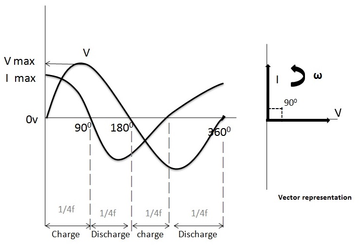
The phasor diagram of AC capacitor is shown in the above figure, here the voltage and currents are represented in sine wave forms. In the above figure we observed that at 00 the charging current is at its maximum value because the voltage is increasing slowly in positive direction. At 900 there is no current flow through the capacitor because at this point the supply voltage is at its maximum peak value.
At 1800 point the voltage slowly decreases to zero and current is at maximum value in the negative direction. Again the charging reaches to its maximum value at 3600, because at this point the supply voltage is at minimum value.
From the waveforms in the above figure we can see that, the current is leading the voltage by 900. Hence we can say that in an ideal capacitor circuit the AC voltage lags the current by 900.
Capacitive Reactance
We know that the current flowing through the capacitor is directly proportional the rate of change of applied voltage but capacitors also offer some form of resistance against the current flow same as like resistors. This resistance of capacitors in AC circuits is called as capacitive reactance or commonly known as reactance. Capacitive reactance is the property of a capacitor opposing the current flow in AC circuits. It is represented with symbol Xc and measured in Ohms same as like resistance.
We need some extra energy over capacitive reactance to charge up a capacitor in the circuit, and the value is inversely proportional to the capacitance value and the frequency of supply voltage.
Xc∝ 1/c and Xc∝ 1/f.
The equation for capacitive reactance and parameters which influences them are discussed in below.
Capacitive Reactance,
XC = 1/2πfC = 1/ωC
Here,
XC = Reactance of capacitor
f = frequency in HZ
C = Capacitance of a capacitor in Farads
ω (omega) = 2πf
From the above equation we understood that capacitive reactance is high where the frequency and capacitance values are at low and at this stage the capacitor acts as a perfect resistor. If the frequency of supply voltage is high then the reactance value of capacitor is low and also at this stage capacitor acts as a good conductor. From the above equation it is clear that the reactance is zero if the frequency is infinity and the reactance value is infinity where the frequency is at zero.
Capacitive Reactance against Frequency
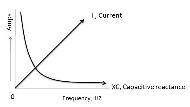
The above figure shows the relation between the capacitive reactance, current and frequency of the supply voltage. The result we observed is that the frequency and reactance are inversely proportional. This means if frequency is high then the reactance is low. The increase in frequency will increase the charging current, and this happens because the rate of change of voltage increases with time. The capacitive reactance is at infinite value where the frequency is zero and vice versa.
AC Capacitance Example No1
Here is a detailed procedure of finding the rms value of current flowing through the circuit with 3uF capacitor that is connected to 660V and 40Hz supply.
Capacitive Reactance,
XC = 1/2πfC
Here,
f = 40HZ
C = 3uF
Vrms = 660V
Now,
XC = 1/(2 × 3.14 × 40HZ × 3 × 10-6) = 1326Ω
Irms = Vrms/XC = 660V/1326Ω = 497mA
AC Capacitance Example No2
Find the rms value of current flowing through the circuit having 5uF capacitor connected to 880V and 50Hz supply.
Capacitive Reactance,
XC = 1/2πfC
Here,
f = 50HZ
C = 5uF
Vrms = 880V
Now,
XC = 1/(2 × 3.14 × 50HZ × 5 × 10-6) = 636Ω
Irms = Vrms/XC = 880V/636Ω = 1.38 A
From the above two examples practically we observed that the reactance of a capacitor depends on the frequency of the supply voltage and it is inversely proportional relation. In example 1 , the reactance is 1326Ω for the frequency of 40HZ but the reactance value decreases to 636Ω when the frequency increases to 50HZ which is shown in example 2.Hence it is clear that the reactance of a capacitor is inversely proportional to the frequency and capacitance.
FAQs
1.
2.
3.
4.
5.
6.
7.
Capacitance in an AC circuit refers to the ability of a capacitor to store and release electrical energy in the form of an electric field. It resists changes in voltage by charging and discharging as the AC voltage alternates.
In an AC circuit, a capacitor continuously charges and discharges as the voltage changes polarity. This creates a phase difference where the current leads the voltage by 90 degrees.
Capacitive reactance (Xc) is the opposition a capacitor offers to the flow of alternating current. It is given by the formula:
𝑋𝐶 = 1/2𝜋𝑓𝐶
where 𝑓 is the frequency in hertz and C is the capacitance in farads.
As the frequency increases, the capacitive reactance decreases, allowing more current to flow. This means capacitors pass high-frequency signals more easily than low-frequency ones.
No, a capacitor blocks direct current (DC) after its plates are fully charged. However, it allows alternating current (AC) to pass through due to the continuous change in voltage direction.
In a purely capacitive AC circuit, the current leads the voltage by 90 degrees. This is due to the capacitor’s charging and discharging behavior.
In series, the total capacitance decreases, and the voltage divides across the capacitors. In parallel, the total capacitance increases, and each capacitor experiences the same voltage.
Summary
Capacitance plays a crucial role in AC circuits by influencing how current and voltage interact over time. Through its ability to store and release electrical energy, a capacitor introduces reactance that affects circuit behavior based on frequency. Understanding capacitance and its effects—such as phase shifts, frequency response, and impedance—helps in designing and analyzing a wide range of electrical and electronic systems, from filters to power supplies.
Having any queries, feel free to post them in the comments section below. We’ll help you to resolve them.

One Response
thanks for the add.. And the cotent here are 100% correct .All i could say is the mavelas.