In this tutorial, we will learn about one of the major applications of a PN Junction Diode as a Flyback Diode or Freewheeling Diode. The diode is such applications may also be called as Suppression Diode, Snubber Diode, Kickback Diode, Clamp Diode etc.
An important point to note is that this tutorial is explained with DC Circuits in mind. In AC Circuits, a special circuit called Snubber Circuit (which is a combination of a capacitor and a resistor) is generally used for the same purpose.
Introduction
Switching inductive loads like motors, relays, transformers (in SMPS), solenoids etc. is an extremely common application. When designing switching circuits for such inductive loads, you need to take special care about high voltage spikes or also known as Inductive Flyback.
Without proper circuit protection embedded in your circuit design, the switches (either mechanical or semiconductor) would be seriously damaged and may result in circuit failure. Before understanding what is an inductive Flyback, how a Flyback diode works and other related aspects, first let us briefly take a look at the working of a Diode.
How a Diode Works?
We know that a diode is a semiconductor switch i.e. a switch that does not require any mechanical motion to change its state. When the diode is forward biased and the voltage is greater than the threshold voltage, the diode acts as a closed switch and a large current flow in the forward direction i.e. Anode to Cathode.
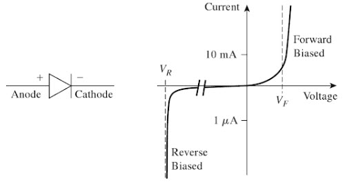
When the diode is reverse biased, very small current (usually in µA) flows and the diode essentially acts as an open switch.
Keeping this in mind, let us proceed with inductive loads and high voltage spikes.
Inductive Loads in DC Circuits
A conductive loop of wire, when subjected to an electric current through it, generates a magnetic field around it. This conductive loop is known as Inductor.
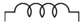
In fact, in case of electronics and circuits, even a small piece of wire or a trace on PCB can also be considered as an Inductor (or an inductive element) as it has inductance i.e. ability to store energy in the form of electromagnetic field.
As mentioned earlier, some of the commonly known devices with inductors (also known as inductive loads) are motors, solenoid, electromagnetic relay, transformer etc.
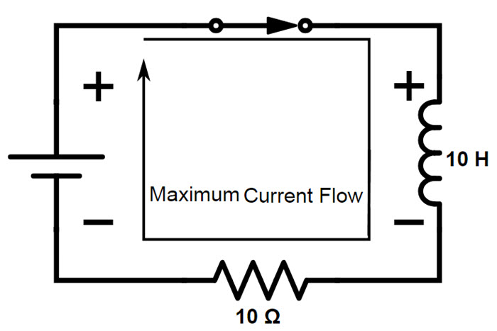
The following circuit shows a simple inductor connected to a DC Power supply with a switch.
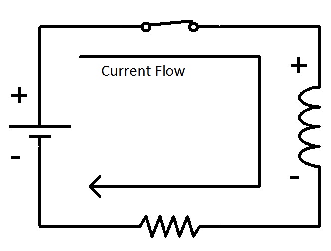
When the switch is closed, the inductor builds up magnetic field and gets fully energized. The current flows from positive terminal of the power supply to the negative terminal through the inductor i.e. the inductor inhibits the flow of current in the circuit while it building up energy.
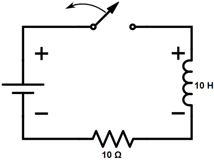
If the switch is now opened, the flow of current is interrupted and the magnetic field starts collapsing. As per Lenz’s law, the collapsing magnetic field induces a current in the circuit but in opposite direction.
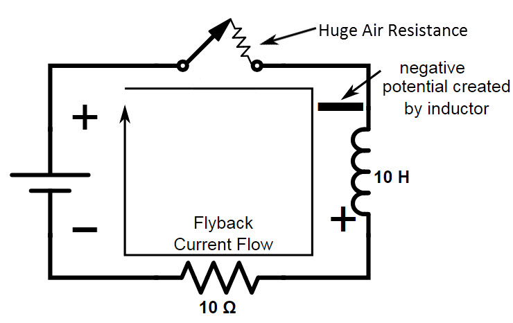
As a result, a negative potential is created on the inductor where there was once a positive potential due to forward flow of current. This is commonly known as Back EMF or Counter EMF or Flyback Voltage.

Now, due to the Flyback voltage, the inductor essentially becomes a power source with a significantly greater potential the actual power supply itself. For a 12V DC Power supply, the Flyback voltage spike can be few hundreds of volts. The high voltage spike is determined by the following equation.
V = L di/dt, where
- V is the voltage across the inductor
- L is the Inductance
- di/dt is the rate of change of current
This means that the faster the current through the inductor is changed, the higher the voltage spike.
Flyback Voltage and its Origin
A Flyback voltage or an Inductive Flyback is a voltage spike created by an inductor when its power supply is removed abruptly. The reason for this voltage spike is the fact that there cannot be an instant change to the current flowing through an Inductor.
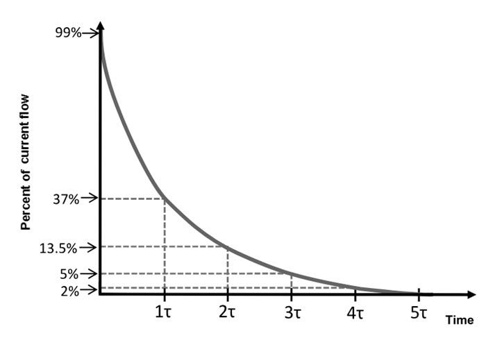
Time Constant of the Inductor determines the rate at which the current can change through an inductor. This is similar to the time constant of a Capacitor, which determines the rate at which its voltage can change.
Time Constant of Inductor τ = L/R, where L is Inductance in Henries and R is series resistance in Ohms.
Similar to a capacitor, it takes nearly 5 time constants (5τ) to dissipate the current in an inductor.
Assume, in the above circuit, the inductor is 10H and the series resistor is 10Ω. So, when the switch is closed, maximum current flows through the inductor.
Now, let us see what happens when the switch is opened suddenly.
First, let us calculate the time constant. Using the formula of time constant and substituting the above assumed values, it is clear that the time constant is 1 second.
So, it will take approximately 5 seconds from the moment the switch is open, to completely stop the flow of current. This means that current flows in the circuit even after the switch is open (assuming it would take a few milli seconds to completely open the switch). How is this possible?
This can be understood from the inductors point of view. The switch gap, which is essentially air, is viewed as a huge resistor by the inductor and the resistance is in the order of few mega Ohms. This means that the circuit is still closed from inductor’s point of view with a huge resistor filling in the air gap.
Now that it is confirmed that the circuit is still closed, the inductor will try to dissipate the current and in order to do so, the inductor will drop voltage across the air gap resistance by reversing its polarity by using the energy stored in it in the form of magnetic field.
Now, the inductor tries to flow current as per its current dissipation curve. This could be problematic according to Ohm’s Law, V = I x R.
Even for a small current, when it is multiplied by the huge air resistance (few hundreds of Mega Ohms) will lead to a very high voltage across the air resistor. This is the origin of the Flyback Voltage or Voltage Spike.
Impact of Flyback Voltage on Switches
As there is no physical resistor when the switch is opened, sparks / arcs will occur between the switch and the other terminal, if a mechanical switch is used. All the energy from the arc is usually discharged across the contacts of the switch in the form of heat.
This could potentially damage the switches permanently or drastically reduce the lifetime of the switches. when speaking of switches, they can be mechanical switches or semiconductor switches like Transistors.
How Flyback Diode can prevent Voltage Spikes?
To protect the switch from being damaged due voltage spikes or inductive Flyback, a Flyback Diode or a Freewheeling Diode is used. The basic idea behind the use of a Flyback Diode is to provide an alternative path for the inductor for its current to flow.
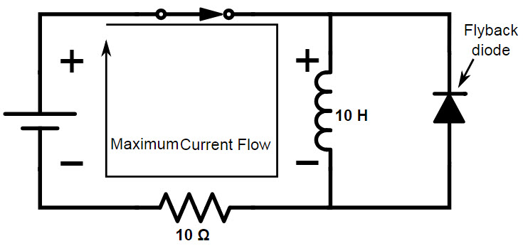
The above image shows the same inductor circuit but with additionally a Flyback Diode. It is important to note that the diode is connected in reverse bias when the switch is closed.
As a result, the diode doesn’t impact the operation of the rest of the circuit when the switch is closed and maximum current flows through the inductor.
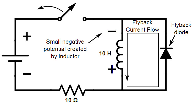
But when the switch is opened, the change in polarity of the inductor will make the diode to be placed in forward bias. Hence, the diode will allow current to flow at a rate determined by the time constant of the inductor.
The resistance of the diode, when it is forward biased, is very less and hence the voltage drop across the diode will be significantly less for the current to flow. This prevents arc at the switching device and as a result protects the switching device from damage.

2 Responses
Whats the value of the flyback diode
Nice article.
But I think the Voltage formula lacks a minus sign indicating the reverse polarity of the induced voltage — -L(di/dt). Some texts claim the minus sigh indicates current drop or interruption. I think its also there to indicate the reverse polarity voltage. If the voltage were the same polarity, we couldn’t use a diode to suppress it.
I also believe the -speed- of field collapse has an effect on the resulting voltage (dt in di/dt). When the flyback diode begins to conduct, current starts to flow, the field collapse is slowed — reducing the amount of flyback voltage generated.
FWIW