Microcontrollers are the heart of embedded systems. There are various types of embedded systems for different applications. The applications of embedded systems range from controlling small DC motors to use in industrial automation. When it comes to controlling high voltage devices, microcontrollers often depend on Relays to drive them. Relays act as a bridge between the low power microcontrollers and high voltage devices.
In this project, we are going to control a Relay using Arduino UNO to drive a high current load like a motor. Although the project is explained to drive a simple motor, similar implementation can be applied to control high voltage alternating current devices.
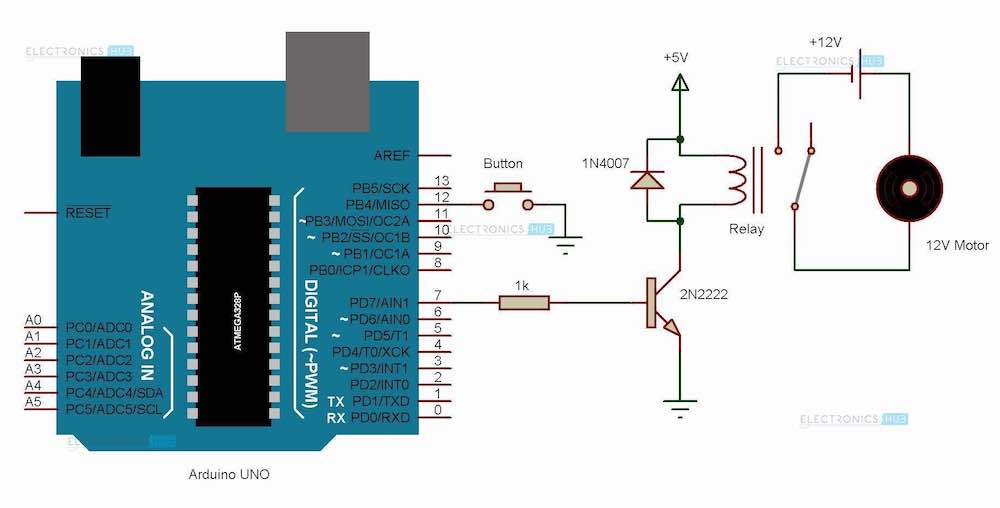
Arduino Relay Control Circuit Diagram
Components
- Arduino UNO
- Relay
- 1N4007 PN Junction Diode
- 2N2222 NPN Transistor
- 1KΩ Resistor
- Push button
- Prototyping board
- Power supply – 5V and 12V
- Connecting wires
Component Description
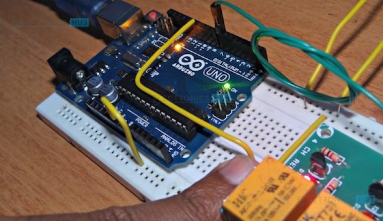
Arduino UNO: As mentioned in the project introduction, a microcontroller is used to drive the relay. Hence, Arduino UNO, which is an ATmega 328P microcontroller based prototyping board, is used in the project.
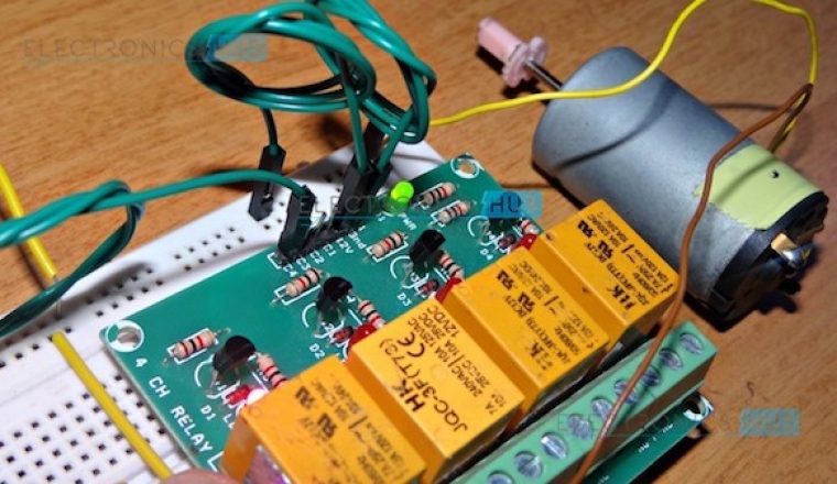
Relay: A relay is a type of switch that provides connection between a low power circuit and a high power circuit. Electromechanical relays are the most commonly used relays and consists of a coil that acts as an electromagnet and moving contacts.
Generally, a relay consists of five terminals: two coil terminals, a common terminal (COMM), a normally open terminal (NO) and a normally closed terminal (NC).
A low power signal from a microcontroller is given to the coil (usually through a transistor) and the other three terminals i.e. NO, NC and COMM are connected to the high voltage supply along with the load. More information about relay and its working.
1N4007 Diode: This diode acts as a flyback or a freewheeling diode in the circuit. Such diodes are often used in inductive circuits. When the power to the circuit is turned off, since the coil in the relay is an inductor, the current in it cannot be changed instantly. In such cases, a freewheeling diode provides a path to the current.
Diodes are often used in DC powered inductive circuits whereas a snubber circuit is used in AC powered inductive circuits.
2N2222 Transistor: It is an NPN transistor generally used for medium power amplifier and switching applications for currents up to 1 A. In this project, it is used as a switch which turns on or off the relay.
Circuit Design
The project is used to demonstrate the high voltage driving capabilities of a relay using Arduino UNO. The design of the circuit is described here.
The base terminal of the 2N2222 transistor is connected to any of the digital I/O pin of the Arduino through a 1KΩ current limiting diode (in this project, base is connected to Pin 7 of Arduino). The emitter terminal of the transistor is connected to ground.
One coil terminal of the relay is connected to the collector terminal of the transistor while the other terminal is connected to supply voltage. The supply voltage to coil terminal of the relay is dependent on the voltage ratings of the relay. Some are rated 5V and other are rated 12V. In this project, it is connected to 5V.
A freewheeling diode is connected across the coil terminals of the relay as shown in the circuit diagram.
When coming to the contact terminals of the relay, a 12V motor along with a 12V power supply are connected in series between the Normally Open (NO) terminal and Common (COMM) terminal as shown in the circuit.
In order to decide when to turn on the relay and when to turn it off, a button is connected between the Pin 12 of Arduino and ground.
Working Principle of the Project
The intention behind the project is to explain how a microcontroller (in this case, an Arduino) can be used to control a high voltage and high current devices using a relay. The principle of working of the project lies in the functioning of the relay and is explained here.
When the system is powered on, the Arduino waits for the button to be pressed (as per the code written). The button terminal is pulled up internally. Hence, when the button is pushed, the Arduino detects a Logic 0 (LOW).
This will send a Logic 1 (HIGH) signal to Pin 7, which is connected to the base of the transistor. As a result, the transistor is switched ON. As one of the coil terminal of the relay is connected to the collector of the transistor (which is switched ON), a conduction path between the supply, coil and collector – emitter terminals of transistor is formed.
Because of this, the coil in the relay gets energized and acts as an electromagnet. As a result, the moving contact of the coil, which was initially in the Normally Closed (NC) position, will be attracted towards the electromagnet and moves to the Normally Open (NO) position. This action will complete the motor circuit and hence, the motor starts rotating.
The motor keeps on rotating as long as the button is pushed. Once the button is released, the transistor is switched OFF and the coil in the relay is de energized. Hence, the contact goes back to the Normally Closed position and the motor is turned OFF.
Caution: One must be very careful when working with relay in AC connection. Even the slightest contact can be dangerous and might be fatal.
Applications
- In this project, an Arduino control of Relay is explained using a high current DC motor.
- As mentioned earlier, the circuit can be extended AC systems. Such circuits can be used to implement AC motor control, home automation, remote control of appliances etc.
- This circuit can also be implement in high power DC systems like motors, servos etc.

3 Responses
If I use D400 transistor will it works.
Hi, I would suggest you to use a Relay Module (like a 2-channel Board). If you do not have one, then yes, you can use this transistor.
nice, I used dpdt relay and work very well, thanks