In this tutorial, we will learn about a simple but effective circuit called the Crowbar Circuit. It is essentially an overvoltage protection circuit. We will take a look at the concept of the circuit, its design using Thyristor / SCR, the working of the circuit as well as some important limitations.
Introduction
Power supplies are an important component in electrical and electronic circuits. They are usually very reliable and can provide good and clean power to the main circuitry. In fact, the life, reliability and longevity of any electronic system is dependent on a good power supply.
If a power supply fails for any reason, then the circuit attached to it will be significantly damaged, sometimes beyond repair. For example, one common problem with linear power supplies is the failure of the series pass transistor.
When there is a short between the collector and emitter terminals of pass transistor, the transistor fails and there will be a very high and unregulated voltage at the output. If this high voltage is given to the main system, then sensitive components like ICs will be damaged due to significant over voltage.
Hence, it is quite common to implement a simple overvoltage protection circuit at the output of the power supply so that in case of unexpected spike in voltage will not cause any damage to the main circuit or the load. This is done by the Crowbar Circuit.
What is a Crowbar Circuit?
A Crowbar Circuit is a simple electrical circuit that prevents damage to the circuits (load of the power supply) in the event of an overvoltage of the power supply. It protects the load by shorting the output terminals of the power supply when a overvoltage is detected.
When the output terminals of the power supply are shorted, the huge current flow will blow the fuse and thus disconnecting the power supply from the rest of the circuit. Hence, in simple terms, the job of the Crowbar Circuit is to detect the overvoltage and blow the fuse (sometimes, a circuit breaker is tripped).
Typically, Crowbar Circuits are designed using Thyristor (SCR) or TRIAC as the main shorting device.
Crowbar Circuit Design
Now that we have a basic understanding of the Crowbar Circuit, we will now proceed to designing one. In this tutorial, I will show two typical designs, one involving a Thyristor / SCR while the other makes use of a TRIAC as the shorting device.
Crowbar using Thyristor
The following image shows the first design using a Thyristor. All the components required to build this circuit are mentioned below.
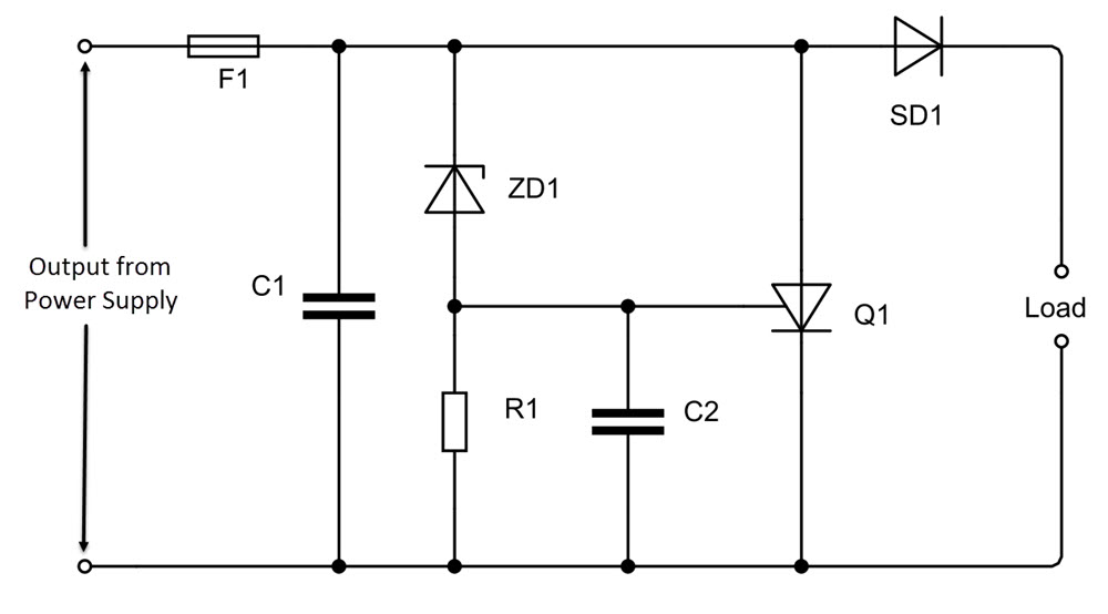
- Thyristor (Q1)
- Zener Diode (ZD1)
- Schottky Diode (SD1)
- Filter Capacitor (C1)
- Snubber Capacitor (C2)
- Pull-down Resistor (R1)
- Fuse (F1)
Working
The working of this circuit is very simple. The Zener Diode (ZD1) is the component that detects the over voltage. Usually, the threshold voltage of the Zener Diode is selected just over the output voltage of the power supply (1V more than the output voltage).
When an overvoltage occurs and if the voltage reaches the threshold voltage of the Zener Diode, then it starts conducting. If the voltage still increases, the voltage drop across the Resistor R1 and the Gate terminal of the SCR (Q1) will increase.
Initially, when the Zener Diode in not conducting, the Resistor R1 acts as pull-down resistor for the Gate terminal of the Thyristor to keep in LOW. But when the Zener Diode starts conducting and the voltage across the resistor R1 increases, the gate voltage also increases.
When the voltage at the Gate terminal is more than its threshold voltage (usually between 0.6V and 1V), the Thyristor starts to conduct and essentially providing a short circuit between the power rails. As a result of this short circuit, the fuse blows.
One important point to remember here is that the current rating of the Thyristor should be more that that of the Fuse. Also, the overall trigger voltage is the sum of Zener Diode threshold voltage and the Thyristor threshold voltage.
There are few other components in the circuit and let us see their purpose in this circuit. First, the Capacitor C1 is a filter capacitor used to reduce noise and small voltage spikes and avoids unnecessary triggering of the circuits.
The Capacitor C2 is a Snubber Capacitor and it prevents accidental triggering of the Thyristor during powerup of the circuits. Finally, the Schottky Diode acts as reverse protection diode to prevent the main circuit from triggering the Crowbar Circuit.
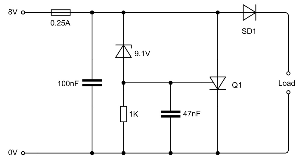
Example
Let us now see an example design of the above circuit using real-time values. Let the output of the power supply be 8V. Then, the threshold voltage of the Zener Diode is chosen to be 9.1V. All the other components and their values are shown in the following image.
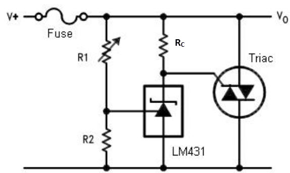
Crowbar using TRIAC
The net design is based on TRIAC as the short circuit device. The Gate of the TRIAC is controlled by an Adjustable Zener Regulator like LM431 from Texas Instruments. Additionally, there are a couple of resistors to set the reference voltage for the Zener Regulator.
Working
Resistors R1 and R2 form a voltage divider and set the reference voltage to the LM431 Adjustable Zener Regulator. Under regular operating conditions, the voltage across R2 is slightly lower than the Reference Voltage (VREF) of LM431 so that it stays off.
By selecting the cathode resistor RC appropriately, the voltage at the gate of the TRIAC will be very less so that it stays off.
When the voltage increases due to overvoltage condition, the voltage drop across the resistor R2 increases beyond the VREF and the LM431 Zener Regulator starts conducting. As a result, the cathode of the LM431 starts to draw current which essentially increases the gate voltage of the TRIAC.
As soon as the gate voltage exceeds the threshold voltage, the TRIAC latches and short circuits the power rails and thus blowing the fuse.
Limitations
A simple Crowbar Circuit is very useful in overvoltage protection and hence it is an essential part of the bench power supplies. Even though this circuit is very useful, there are some limitation that we must take a note off.
In the Thyristor based design, the trigger voltage is set by the Zener Diode and it usually not adjustable. Hence, selecting the right Zener Diode is very important. The trigger voltage of the circuit should be slightly above the output voltage of the power supply so that spikes and noise might not accidentally trigger it.
When the power supply is used in RF Designs, like an RF Transmitter, proper filtering of the power lines before and after the transmitter must be used.
In the event of overvoltage, the circuit triggers and blows the fuse. Hence, fuses are to be replaced every time an over voltage occurs.
