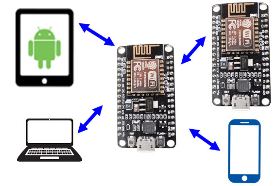
In this tutorial, I will show How to Build a Simple ESP8266 Web Server. This ESP8266 NodeMCU standalone Web Server can be accessed by any device in the local network that has a web browser (Mobiles, Laptops, Tablets). To demonstrate the working of the web server is ESP8266, we will create a web page which controls two LEDs.
What is a Web Server?
A Web Server is combination of Hardware and Software which is responsible for maintaining, fetching and serving web pages to Web Clients. The information in the web pages can be Text in the form of HTML Documents, Images, Video, Applications etc.
Web Browsers in your laptops and mobile phones are web clients. If you observed the terms Web Server and Web Client then yes, this type of communication is called as Client – Server Model.
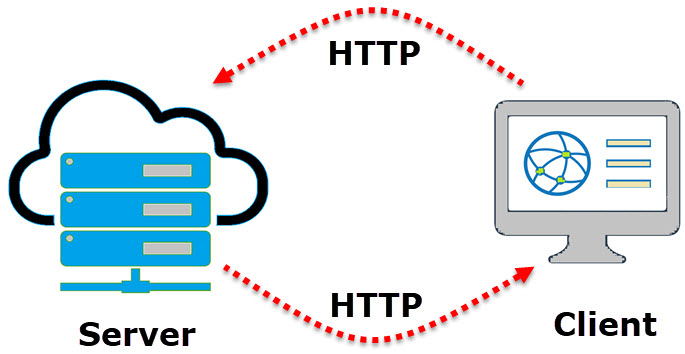
The communication between Client and Server is implemented using a special protocol called HTTP or Hyper Text Transfer Protocol. In this type of communication, the Web Client makes a request for information from the server using HTTP. The Web Server, which is always waiting (listening) for a request, responds to the client’s request with appropriate web page.
If the requested page is not found, then the server responds with HTTP 404 Error.
Requirements of ESP8266 Web Server
With the brief introduction of Web Servers in general, we will now understand what are the requirement of a standalone ESP8266 Web Server. An ESP8266 Web Server must contain a web page in the form of HTML Text.
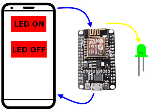
When a client, like a web browser in a mobile phone, sends a request for that web page over HTTP, the web server in ESP8266 must respond with the web page. Additionally, when the client performs any operations, like clicking on a button, the server should respond with appropriate actions (like turning ON / OFF an LED).
Wi-Fi Modes of Operation of ESP8266
Before proceeding with creating a Web Server for ESP8266, we will take a look at the different operating modes of Wi-Fi in ESP8266. If you remember the How to Connect ESP8266 to WiFi tutorial, I already discussed about these modes. But for this web server tutorial, we will revise them once again.
Basically, the ESP8266 Wi-Fi Module operates in three WiFi operating modes. They are:
- Station Mode (STA)
- Soft Access Point Mode (AP)
- Station + Soft AP Mode
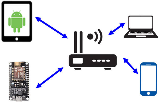
In station mode, the ESP8266 Module connects to an existing WiFi Network, which is setup by a Wireless Router, just like our Mobile Phones and Laptops.
The ESP8266 Wi-Fi Module connects to a Wi-Fi Network of Router using the router’s SSID and Password and the router assigns the local IP Address for ESP8266.
Coming to Access Point Mode, the ESP8266 Module creates its own WiFi Network like a Wireless Router, so that other stations like Mobile Phones, Laptops and even other ESP8266 modules (in STA Mode) can connect to that network.
Since ESP8266 doesn’t have a Wired Ethernet connectivity to internet, this AP Mode is called as Soft AP Mode. While configuring ESP8266 in AP Mode, you have to set the SSID and Password for the network, so that other devices can connect to that network using those credentials.
Station + Soft AP is a combination of Station Mode and Soft AP Mode. In this, the ESP8266 acts as both the Station as well as an Access Point.
Which Mode to use for Creating Web Server?
You can configure ESP8266 Wi-Fi Module either in Station Mode or in Access point Mode to create a web server. The difference is that in station mode, all the devices (Mobiles, laptops, ESP8266, etc.) are connected to Wireless Router’s WiFi Network and IP Address to all the devices (including the Web Server of ESP8266) is assigned by the router.
Using this IP Address, clients can access the Web Page. Additionally, the clients do not lose internet connectivity from the Router.
But if we create Web Server for ESP8266 in AP Mode, then clients must connect to the network provided by ESP8266 using its own SSID and Password in order to access the Web Pages. Since it is a soft AP Mode, clients do not have internet connectivity.
Creating ESP8266 Web Server either in Station Mode or in Soft AP Mode is very similar except the configuration part of the ESP8266.
In this tutorial, I will show you how to create a Web Server on ESP8266 configured in Station Mode (STA).
NodeMCU ESP8266 Web Server
Apart from creating the web server on ESP8266 and accessing it on clients, we will also see how Server responds to different requests for clients by controlling two LEDs connected to GPIO Pins of ESP8266 NodeMCU Board.
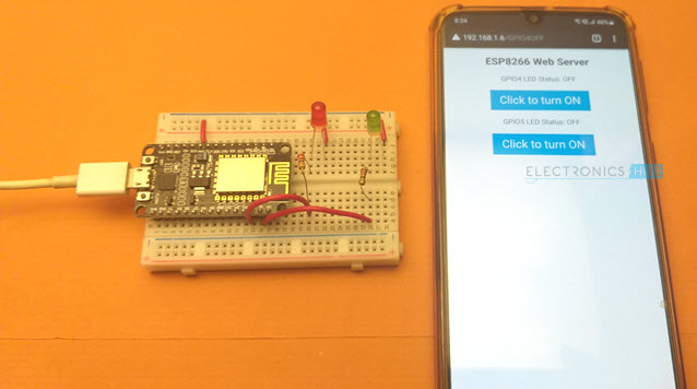
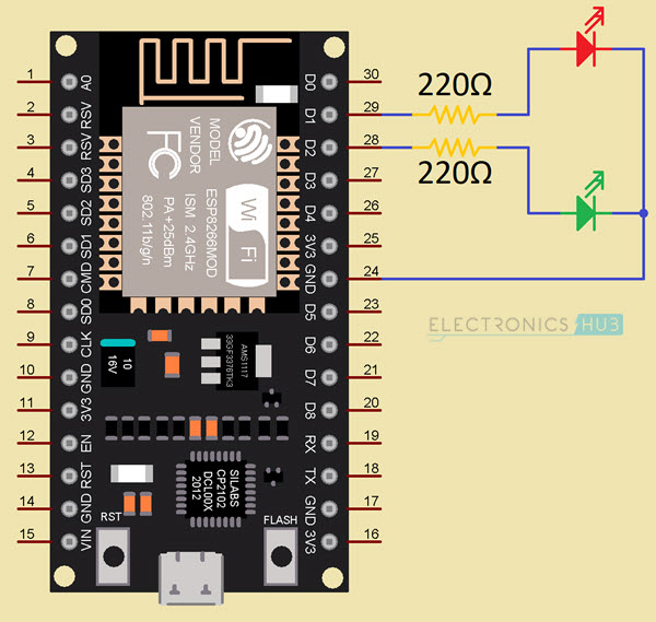
To demonstrate this, I connected two 5mm LEDs to GPIO4 and GPIO5 of ESP8266 through respective current limiting resistors (220Ω). GPIO4 is labelled D2 and GPIO5 is labelled D1 on NodeMCU.
Code
Coming to the important and interesting stuff, the actual code for Web Server on ESP8266. It is just an HTML Code with some text, couple of buttons and some stylization.
The following block shows the complete code for ESP8266 Web Server. I will explain the code in the next section.
Modify and Upload Code
In lines 6 and 7 of above code, you have to make the modifications as per your Wi-Fi Network Settings. These are the SSID and Password of the Wi-Fi Network.
const char* ssid = "ESP8266-WiFi"; /* Add your router's SSID */
const char* password = "12345678"; /*Add the password */
After making necessary modifications, make the necessary connections as per the circuit diagram, connect the NodeMCU to the computer, select the right COM Port and upload the code.
If you are new to ESP8266 and NodeMCU, then the Getting Started with NodeMCU tutorial will help you in configuring Arduino IDE.
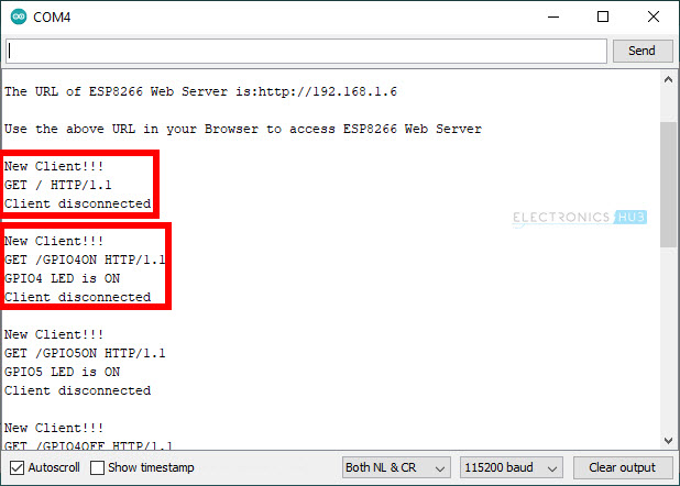
Open the Serial Monitor and ESP8266 NodeMCU will print some important information like the progress of Wi-Fi Connection, IP Address and URL of Web Server (which is essentially the IP Address of the ESP8266).

So, in my case the IP Address of ESP8266 is 192.168.1.6.
Accessing the ESP8266 Web Server from Clients
Open a Web Browser either in a laptop or mobile phone and type the IP Address. This is the moment of truth. If everything goes well, then you should be able to see a simple web page hosted by the ESP8266 Web Server.
The following is a screenshot of Chrome Web Browser on a laptop accessing the Web Server of ESP8266.
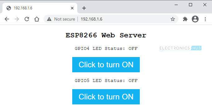
As you can see from the image, the web page displays a main header text, followed by status of the LED connected to GPIO4. This is followed by a Button, which can be used to turn ON or OFF the LED. The same stuff again for GPIO5 (status followed by Button).
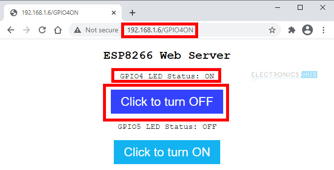
Now, if I click on the first button, the LED connected to GPIO4 will turn ON, the status is updated in the web page, the text and color of the Button is also changed.
If you take a look at the Serial Monitor, every time a client tries to connect (or send a request), some key information is printed on the serial monitor. I will explain about this information (this is actually a part of request from client) in the next section.
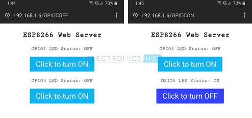
Next, I tried the same thing on a Mobile Phone. It works perfectly.
NOTE: All the clients i.e., mobiles, laptops, etc., must be connected to the same network as the ESP8266 Module.
How ESP8266 NodeMCU Web Server Works?
Let us now try to understand How ESP8266 Web Server works by analyzing the code. I will explain all the important parts of the code and leave the simple stuff (like turning ON LED) for your exploration.
Initial Setup
First, you need to include only one header file related to the ESP8266WiFi Library.
#include <ESP8266WiFi.h>
Next, assign the GPIO pins to connect two LEDs. I used GPIO4 and GPIO5.
#define gpio4LEDPin 4
#define gpio5LEDPin 5
As I mentioned earlier, add the SSID and Password of your Wi-Fi Network here.
const char* ssid = "ENTER_YOUR_SSID";
const char* password = "ENTER_YOUR_PASSWORD";
Since we want to create an HTTP Server, we have to setup the Web Server with port number 80 (this is the default port for HTTP Servers).
WiFiServer espServer(80);
Next, in the setup() function, begin serial communication with baud rate of 115200 and configure the GPIO pins as OUTPUT. Also initialize the GPIO pins to LOW.
Serial.begin(115200);
pinMode(gpio4LEDPin, OUTPUT);
pinMode(gpio5LEDPin, OUTPUT);
digitalWrite(gpio4LEDPin, LOW);
digitalWrite(gpio5LEDPin, LOW);
WiFi.mode(WIFI_STA);
WiFi.begin(ssid, password);
while(WiFi.status() != WL_CONNECTED)
{
Serial.print("*");
delay(500);
}
Serial.println("Starting ESP8266 Web Server...");
espServer.begin();
Serial.println("ESP8266 Web Server Started");
Serial.print("\n");
Serial.print("The URL of ESP8266 Web Server is: ");
Serial.print("https://");
Serial.println(WiFi.localIP());
This completes the initial setup of the Web Server.
Waiting for Client and Responding
Next, in the loop() function, the Server checks if any client wants its service. If there is no client, check again. If there is a request from a client then proceed with response with request.
WiFiClient client = espServer.available();
if(!client)
{
return;
}
When a client enters the IP Address of ESP8266 in its browser, the Server responds back with a simple web page. This is the first request – response, so there will not be any GPIO action. The request from the client is in the form of HTTP GET Method.
You can see in the following image the serial monitor output of the first request from the server i.e., the client enters the IP Address in its browser. The request was “GET / HTTP/1.1”. The “1.1” at the end is the version of HTTP.
If the client is able to open the web page successfully, then the web server is working properly and the HTTP Communication between client and server is successful. Now, depending on the status of the LED, the buttons perform two actions. If the LED is OFF and we click on the button, the client sends a request to turn ON the LED and vice-versa.
To differentiate between the two requests, we used two URLs for the same button click that gets sent to the server based on the status of the LED. So, for both the LEDs, we have a total of four URLs. They are:
- /GPIO4ON
- /GPIO4OFF
- /GPIO5ON
- /GPIO5OFF
Using these URLs, the client sends the request and the format of the request will be in the following forms:
- GET /GPIO4ON HTTP/1.1
- GET /GPIO4OFF HTTP/1.1
- GET /GPIO5ON HTTP/1.1
- GET /GPIO5OFF HTTP/1.1
The next piece of code resolves this request from the client and performs necessary action i.e., making GPIO4 or GPIO5 LOW or HIGH.
if (request.indexOf("/GPIO4ON") != -1)
{
Serial.println("GPIO4 LED is ON");
digitalWrite(gpio4LEDPin, HIGH);
gpio4Value = HIGH;
}
if (request.indexOf("/GPIO4OFF") != -1)
{
Serial.println("GPIO4 LED is OFF");
digitalWrite(gpio4LEDPin, LOW);
gpio4Value = LOW;
}
if (request.indexOf("/GPIO5ON") != -1)
{
Serial.println("GPIO5 LED is ON");
digitalWrite(gpio5LEDPin, HIGH);
gpio5Value = HIGH;
}
if (request.indexOf("/GPIO5OFF") != -1)
{
Serial.println("GPIO5 LED is OFF");
digitalWrite(gpio5LEDPin, LOW);
gpio5Value = LOW;
}
Actual Web Page
The last and the intriguing part of the code is for the actual web page itself. As I mentioned earlier, the web page is designed to be an HTML Text with some information and a couple of buttons (CSS Style).
In the first few lines of code, we are essentially configuring the type of Server and also the type of documents this server hosts.
client.println("HTTP/1.1 200 OK");
client.println("Content-Type: text/html");
client.println();
client.println("<!DOCTYPE HTML>");
The next two lines are needed to make the web page to be accessible on any browser (mobile, laptop) and also prevent requests from favicon.
client.println("<meta name=\"viewport\" content=\"width=device-width, initial-scale=1\">");
client.println("<link rel=\"icon\" href=\"data:,\">");
Now comes the button styling part of the code. The next few lines are CSS styling for buttons and the overall web page like font, font size, color of the button etc. This part is not necessary but it makes the web page more appealing.
client.println("<style>");
client.println("html { font-family: Courier New; display: inline-block; margin: 0px auto; text-align: center;}");
client.println(".button {border: none; color: white; padding: 10px 20px; text-align: center;");
client.println("text-decoration: none; font-size: 25px; margin: 2px; cursor: pointer;}");
client.println(".button1 {background-color: #13B3F0;}");
client.println(".button2 {background-color: #3342FF;}");
client.println("</style>");
Next is the code for actual body of the web page. First, it contains a simple header saying “ESP8266 Web Server”. This is followed by a text indicating the status of LED connected to GPIO4. Following this is the button for GPIO4 with an interactive text on it.
The LED status text and the button is also repeated for GPIO5 as well.
client.println("<body>");
client.println("<h2>ESP8266 Web Server</h2>");
if(gpio4Value == LOW)
{
client.println("<p>GPIO4 LED Status: OFF</p>");
client.print("<p><a href=\"/GPIO4ON\"><button class=\"button button1\">Click to turn ON</button></a>  </p>");
}
else
{
client.println("<p>GPIO4 LED Status: ON</p>");
client.print("<p><a href=\"/GPIO4OFF\"><button class=\"button button2\">Click to turn OFF</button></a></p>");
}
if(gpio5Value == LOW)
{
client.println("<p>GPIO5 LED Status: OFF</p>");
client.print("<p><a href=\"/GPIO5ON\"><button class=\"button button1\">Click to turn ON</button></a></p>");
}
else
{
client.println("<p>GPIO5 LED Status: ON</p>");
client.print("<p><a href=\"/GPIO5OFF\"><button class=\"button button2\">Click to turn OFF</button></a></p>");
}
client.println("</body>");
Finally, close the connection with the client using the following line of code.
client.stop();
Modifying the Code for ESP8266 AP Mode Web Server
If you want to create a web server in which the ESP8266 is acting as an Access Point (Soft AP), then you can still use the previous code but with slight modifications.
The first important thing to modify is the SSID and Password. In STA Mode (station mode), we enter the SSID and Password of the Router. But in AP mode, we have to create a Wi-Fi Network using ESP8266 with its own SSID and Password so that clients can connect to this network.
For example, you can put the SSID as “ESP8266-WIFI” and password as “12345678”. This SSID will be visible to clients and in order to connect to this network, use the above password.
const char* ssid = " ESP8266-WIFI ";
const char* password = "12345678";
Next is the IP address, gateway and subnet. This information is necessary for ESP8266 in AP Mode in order to create a Wi-Fi Network.
IPAddress ip(192,168,1,1);
IPAddress gateway(192,168,1,1);
IPAddress subnet(255,255,255,0);
Now, we can initialize the ESP8266 in AP Mode and also configure its IP address using the following two lines.
WiFi.softAP(ssid, password);
WiFi.softAPConfig(ip, gateway, subnet);
Conclusion
A complete step-by-step tutorial on how to create a Web Server using ESP8266 NodeMCU Board. You learned some important basics about web servers, different modes of operation of ESP8266, how to build ESP8266 Web Server and how to access this server from different clients.

7 Responses
NICE IT WORKS ! THANKS
Thank you.
Is it possible to have the complete code as one piece of software?
Best regards
We are going through some changes in the design of the website. Code section will be updated as soon as possible.
Very good explanation and well written code.
Hi. Is it possible to supply complete code when ESP is used as AP.? I have made changes as suggested, but serial monitor stays stuck on “Connecting to WSP8266 WiFI ************”
It’s a nice article. I enjoyed reading it.
Kindly share the Program (Experimental: Controlling LEDs) in which ESP8266
works in (AP+STA) mode.
Regards
Prof.K.R.Rao
nice article