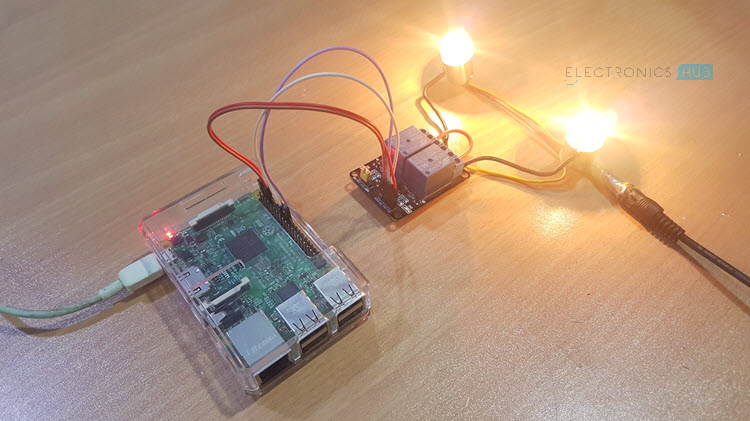
In this project, we will learn about Relay and Relay Module, interface a Relay with Raspberry Pi and see how to control a Relay using Raspberry Pi. This project could be your first step in implementing your own Home Automation Project using Raspberry Pi.
Overview
Home Automation is one of the popular DIY Projects that hobbyists and electronics enthusiasts love to work on. Part of such home automation projects is to control an electrical load like a light bulb or a ceiling fan.
The main concept of Home Automation using Raspberry Pi (or any other platform like Arduino) is to control different electrical loads using Raspberry Pi. In order to do this, you need to understand How to Control a Relay using Raspberry Pi, as Relay is the main component in controlling electrical loads.
If you a little bit of experience in electronics, you might have already known about the importance of Relays. In case you are a beginner in electronics, then I’ll explain what a Relay is, and how can you use a Relay Module with Raspberry Pi or Arduino.
Similar Project: HOW TO USE 5V RELAY ON ARDUINO?
A Brief Note on Relay and Relay Module
What is a Relay?
In layman terms, a relay is a switch. Technically speaking, a relay is an electromagnetic switch where a small control signal (usually from a microcontroller) at the input of the Relay will control a high voltage supply (usually AC mains).
Since this is a Raspberry Pi based project, let us talk with respect to Raspberry Pi. The Raspberry Pi computer, although a powerful device, works on a 3.3V Logic.
If you want this powerful computer to control your electrical loads, like an LED strip running along your garden or kitchen, you cannot interface them directly as the electrical loads work on AC Mains supply and the Raspberry Pi works on 3.3V DC (technically).
Here comes the Relay. A simple electromechanical device that consists of a coil and few electrical contacts. When the coil is energized, it acts as an electromagnet and closes a switch. If the coil is de-energized, the coil loses its magnetic nature and releases the switch.
So, by controlling the coil, you can control a switch, which in turn will control an electrical load. You can control the coil of the relay with the help of Raspberry Pi (although not directly, but with additional circuitry) as all you need is a small current to energize the coil.
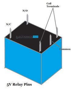
The following image shows a typical 5V Relay. It has 5 pins namely: NO (Normally Open), NC (Normally Closed), COMM (Common) and two coil terminals.
Relay Module
Even though the Relay Coil needs a small current in order to get energized, driving it directly from Raspberry Pi (for that matter, any Microcontroller like 8051 or Arduino) is not a good idea.
A simple way is to drive the Relay Coil through a Transistor. The following image shows the connections required with respect to a Relay.

The circuit shown above will drive a relay with minimum number of components (a Transistor, a current limiting resistor, a Relay and a Diode).
If you have all these components, then you can build the circuit yourself. But if you feel that this might be tedious job, we have an alternative: a Relay Module.
A Relay Module is a simple circuit board that consists of the relay itself and all the necessary components that are required to drive a relay and also the required connectors to connect the load.
I have used a two channel relay module in this project. It is basically, two relays with all the circuitry on a single board.
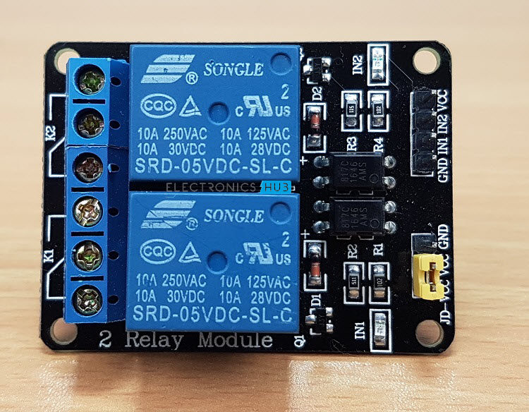
I suggest you to pick up a relay module like this one as you might be dealing with AC Supply in a future project and connecting with screw terminals will make your job easy.
How to Control a Relay using Raspberry Pi?
Till now, we have seen about relay, what is the necessity of relays, how relay works and also about relay modules. Now comes the interesting part i.e. How to Control a Relay using Raspberry Pi?
If you understood the concept of a relay, then it might be clear that all you need to do is to control the coil of the relay i.e. if the Raspberry Pi wants a load to be turned ON, then activate the relay by energizing the coil (sending a HIGH signal from Raspberry Pi).
Similarly, if the Raspberry Pi wants to turn the load OFF, then de-energize the coil by sending a LOW signal.
Circuit Diagram
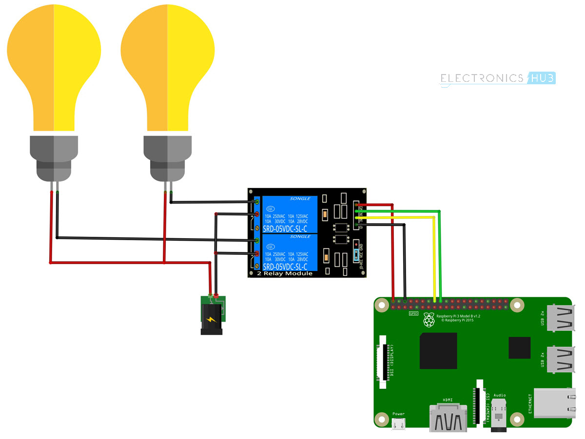
The following image shows the connections with respect to the project of How to Control a Relay using Raspberry Pi.
Components Required
- Raspberry Pi 3 Model B
- 2-Channel Relay Module
- Two Small Incandescent Bulbs (for demonstration in the output)
- Connecting wires
- Power Supply
- Computer
Circuit Design
Connect the inputs to the two relay channels to GPIO16 and GPIO18 of the Raspberry Pi. Then connect the loads as shown in the circuit diagram.
CAUTION: To keep this project simple, I haven’t connected any AC Loads (like a CFL Bulb) to the Relay Module. But if you want to control an electrical load, be extremely careful when connecting to AC Mains supply. If needed, take help from an expert.
Code
The Python Script for the project How to Control a Relay using Raspberry Pi is given below.
Working
The main concept behind this project is to understand the working and use of a relay and also control a relay using Raspberry Pi.
There is nothing special going in the project. All you need to do is to control the GPIO pins connected to the Relay Module. If the GPIO Pin is made HIGH, the corresponding load will be switched ON.
To turn OFF the load, make the GPIO pin LOW.
Applications
- By controlling a Relay with Raspberry Pi, you can control different electrical loads like:
- Lights
- Fans
- LED Strips
- Also, you can implement a Home Automation Project using Raspberry Pi with an additional feature of controlling the load from the internet.

9 Responses
Helpful…
Thanks for the article, most helpful!
I have a further question. I want to control a simple AC motor with a relay, but I want to be able to switch polarity at random intervals so the motor spins in the opposite direction then back again (its for a holiday yard display). Do you use 2 relays and reverse the polarity to each and drive the use of each of the relay via Python from one to the other? In other words, only letting one relay be closed at a time. Can you foresee a problem with switching off on the relays to keep only 1 on at a time?
Thanks for your help!
Tad
A “simple” AC motor does not change its direction of rotation when reversing the polarity. For this you need a three-phase motor.
You will need to use an H bridge motor driver to achieve this.
How many can I use on the rp 4? I was hoping for up to 256 = 2^8
Hi, you’d be best off using DC motors at a low voltage, say 12V DC. You could run the motors from an old car battery and you won’t run into issues with it getting wet. To change direction you need a “Change Over” relay. They have typically two outputs from the contacts. In de-energised mode one set of contacts is powered with +ve on contact one and -ve on contact two. The. In the energised state the +ve and -ve appears on the opposite contacts. This would reverse the motor rotation. Bear in mind that at the point the motor reverses direction, it’ll pass through a stall state which will draw a lot of current. The contacts on the relay may become welded together. Hope that helps.
Use a shift register, pretty much sky’s the limit.
How can we control the brightness of the LED or control say speed of a fan using the above-mentioned circuit, or how can we value of the output voltage?
For variable speed/brightness you will need to use PWM, relays aren’t really suitable for this application.