In this project, I will discuss a little bit about Timers in 8051 Microcontroller and also how to Generate a Delay using 8051 Timers.
Generation of time delay is most important concept in embedded systems. Most of the times, we need to generate precise time delay between two actions in any microcontroller applications. We can generate the time delay using the techniques like LOOPs or by using in built delay functions.
But these are not precise methods for generating time delay so that we will go for timers to produce accurate time delay. This concept is similar to Time Delay Relay concept.
Principle behind the Project
Most of the controllers have inbuilt timers. These timers are not only used for generating time delay but also used for counting purpose. The value of the counter is incremented by 1 when an action or an event occurs.
Timers on the other hand are used to generate delays. Timers in a microcontroller are controlled by the SFRs (Special Function Registers). Timers in different mode of operations are configured by special function registers.
The main principle behind this project is to generate a Delay using 8051 Timers with the help of its Special Function Registers.
Get an idea about How to Interface DC Motor with 8051 Microcontroller?
Circuit Diagram
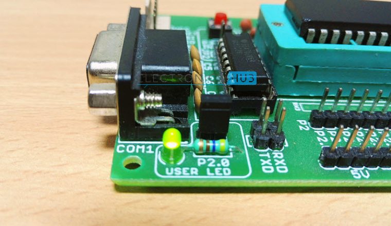
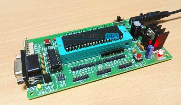
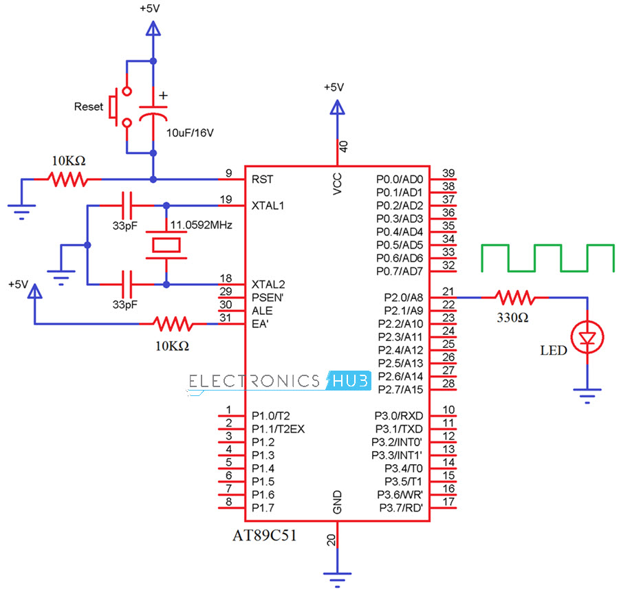
Even though external components (except the oscillator) do not have much in generating delay, I have made a simple circuit, where I will be Blinking an LED ON and OFF with a Delay of 1 second and this delay will be generated with the help of 8051 Timers.
 Components Required
- AT89C51 Microcontroller
- 8051 Programmer
- Programming Cable
- LED
- 330Ω Resistor
- 2 – 10KΩ Resistor
- 10μF/16V Capacitor
- 2 – 33pF Capacitors
- 11.0592MHz Crystal
- Push Button
Circuit Design
The major component in this circuit is AT89C51 controller. A reset circuit for 8051 Microcontroller is made up of a Push Button, a 10KΩ Resistor and a 10μF Capacitor.
A 11.0592MHz uartz Crystal and two 33pF Ceramic Capacitors form the oscillator circuit of the 8051 Microcontroller and are connected to Pins 18 and 19.
Finally, an LED is connected to the P2.0 through a 330Ω resistor to indicate the time delay.
8051 Timers Register Description
TMOD Register
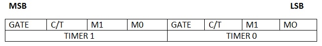
The upper nibble (TMOD.7 to TMOD.4) is used to configure timer1 and the lower nibble (TMOD.3 to TMOD.0) is used to configure timer0.
GATE: If this pin is high, then corresponding timer is enabled when there is an interrupt at corresponding INT pin of the microcontroller.
C/T: This pin is used to select timer or counter. If this pin is high, then used as a counter to count the external event. If this pin is low, then used as a timer to produce time delay.
M1 and M0: These bits are used to select the different timer modes.
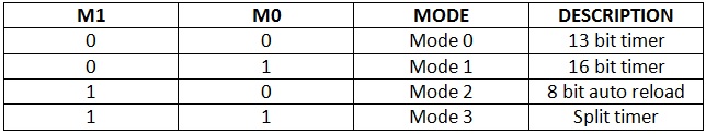
13 Bit Timer: This mode uses 8 bits from high byte and remaining 5 bits from low byte. The value of the timer in this mode is from 0000H to 1FFFH
16 Bit Timer: This mode is most commonly used for producing the time delay. In this mode all the 16 bits are used for timer and values vary from 0000H to FFFFH.
If the value XXXXH is loaded into the timer register, then the produced time delay is equal to the [(FFFFH – XXXXH+1)*(period of one clock pulse)].
The time period of one clock pulse is equal to the 1.085μs 11.0592 MHz frequency.
8-bit Auto Reload: In this mode, initial value is loaded in to the high byte and the same value is loaded into the low byte. Timer value is from 00H to FFH. This mode is used to set the baud rates for serial communication.
Split Mode: In this mode timer is divided in to two 8 bit timers. These 8 bit timers can count from 00H to FFH. This mode is used in the applications where we require an additional 8 bit timer or counter.
TCON Register
It is a special function register used to control the timer operation. In this register only upper nibble is used to control the timer and remaining bits are used for interrupt control.
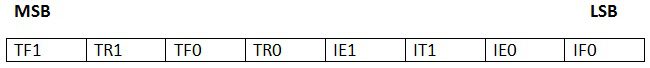
- TF1: This bit is set to 1 automatically on the timer 1 overflow.
- TR1: This bit is used to enable the timer 1. This pin must be high to enable the timer1.
- TF0: set to one automatically when timer0 overflows.
- TR0: place 1 in this bit to enable the timer 0.
Steps for generating precise Delay using 8051 Timers
In order to produce time delay accurately,
- Divide the time delay with timer clock period.
NNNN=time delay/1.085μs
- Subtract the resultant value from 65536.
MMMM=65536-NNNN
- Convert the difference value to the hexa decimal form.
MMMMd = XXYYh
- Load this value to the timer register.
TH=XXh
TL=YYh
Delay Function to Generate 1 ms Delay
In order to generate a delay of 1ms, the calculations using above steps are as follows.
- NNNN = 1ms/1.085μs ≈ 922.
- MMMM = 65536-922 = 64614
- 64614 in Hexadecimal = FC66h
- Load TH with 0xFC and TL with 0x66
The following function will generate a delay of 1 ms using 8051 Timer 0.
Code for LED Blinking using Timers
To demonstrate the functioning of the delay using 8051 Timers, I will blink an LED with a period of 2 seconds i.e. LED will be ON for 1 second and OFF for 1 second.
Circuit Simulation Video
How to Operate?
- Initially burn the program to the AT89C51 controller
- Give the connections as per the circuit diagram
- Switch on the supply, now you can observe the toggling of LED with some time delay.
- If you connect the output to an oscilloscope you can observe the square wave.
Circuit Applications
- Used in embedded system applications where we want precise time Delay.
- This system used to generate square wave.
- Used in Ultrasonic module applications.

3 Responses
good day for today for you. my question is how to download the code please reply
please i need only code for thiis project
i create loop of 1000 to get 1 sec but it give 2sec delay why so???????????