A Relay is an electromechanical device that acts as a switch between two terminals. The switching operation is achieved by energizing or de energizing the coil in the relay.
A small electrical signal from a microcontroller or other device will do this work. There are some special types of relays in which the switching action is not immediate for energizing and de-energizing of the coil.
These relays provide a “Time Delay” between the energizing or de-energizing of the coil and movement of the armature. Such relays are called Time Delay Relays.
A Time Delay Relay consists of a normal electromechanical relay along with a control circuit to control the relay operation and timing.
The main difference between a regular relay and a time delay relay is that in case of a normal relay, the contacts are close or open immediately when the coil is energized or de-energized while in case of time delay relay, the contacts are close or open only after the preset time interval.
In this project, a simple 12V Time Delay Relay is designed using a regular electromechanical relay and some additional circuit to provide the timing function.
[Read: Adjustable Timer Circuit]
How To Build Time Delay Relay Circuit
Circuit Diagram
Components Required
- 12V Relay — 1
- TIP122 — 1
- 1N4728A (3.3V Zener) — 1
- 100 KΩ POT — 1
- 1KΩ — 3
- 330Ω — 1
- 1000µF / 25V — 1
- 100µF / 25V — 1
- 1N4007 — 1
- LEDs — 2
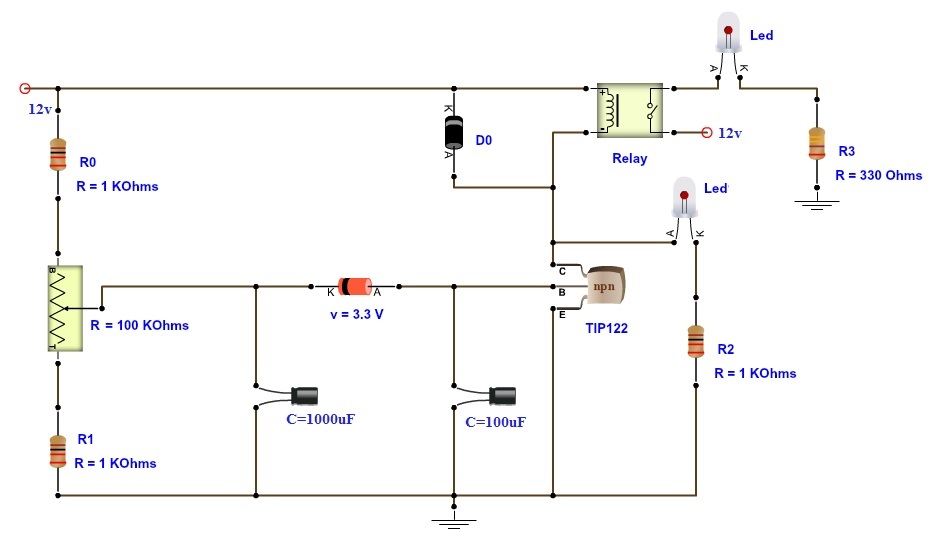
Circuit Design of Time Delay Relay
A 1KΩ resistor, a 100KΩ variable resistor and another 1KΩ resistor are connected in series between the supply and ground.
The wiper of the variable resistor is connected to the positive terminal of a 1000µF capacitor. The wiper terminal of the variable resistor is also connected to the cathode of the Zener diode.
Anode of the Zener diode is connected to positive terminal of 100µF capacitor. Anode of Zener diode is also connected to the base of transistor TIP122.
Negative terminals of both the capacitors and the Emitter terminal of the transistor are connected to ground.
One end of the relay coil is connected to the Collector terminal of the transistor and the other end of the coil is connected to supply.
A diode is placed between the coil terminals. An LED along with a current limiting resistor is connected from the collector of the transistor.
To show the switching operation of the relay, an LED is connected to Normally Open contact of the relay and the Com contact is connected to supply.
Working of Time Delay Relay
Modern day electronic devices use SMPS based power supply systems. Such power systems are vulnerable to spikes in mains power supply.
Input surge current at power on or power resuming after failure can cause severe damage to SMPS systems in electronic devices.
Hence, it is safe to provide a time delay before giving the power to device. This prevents the disastrous effects of voltage spikes or input surge currents.
The aim of this project is to demonstrate the functioning of a time delay relay. Time Delay Relay can provide a short delay after power is turned on and before switching on the device.
The working is very simple and is explained below.
The circuit is based on the RC time delay and Zener controlled switch. When the power to the circuit is turned on, the 1000µF capacitor charges through the 100KΩ variable resistor.
Once the charge across the 1000µF capacitor reaches 3.3V, Zener diode starts conducting.
As the Zener is connected to the base of the transistor, it triggers the transistor and it is turned on. The relay coil is connected to collector of the transistor.
Hence, the relay coil gets energized when the transistor is switched on. As a result, the contacts of the relay switch.
The 100µF capacitor that is connected to the base of the transistor, is used to keep a stable base bias of the transistor so that there are no relay clicking.
The delay of the relay can be controlled by variable resistor and 1000µF capacitor. For shorter delays, the circuit works fine but for longer delays, a 12V relay may be unstable and oscillations of the armature can be found.
For longer delays, it is advised to use a 6V relay with a 100Ω resistor in series with the coil must be used. This will stabilize the armature operation even for longer delays.
When the variable resistor is kept at 20KΩ, the delay is about 8 seconds.
NOTE
- A simple time delay relay circuit is designed here. With the help of this circuit, a user controlled delay to relay can be given.
- Time delay relays are very useful in protecting sensitive electronic devices from spikes and surges.

14 Responses
what is the time equation in this circuit plz tell me
The equation for the Time Constant is TC = RxC. This is the time taken by the capacitor C to charge to 63.2% of the supply voltage through R.
i need a simple circuit that has four resistors,a potentiometer(variable resistor) a diode and an n-p-n transistor.It operates on 24v d.c and wil cut-off after 10s seconds.
Hi, You need a capacitor in the circuit. Without capacitor, you wont get the delay (charge and discharge).
Can this same circuit be used to function with a 5V supply rather than a 12V one, while still using the same component values?
Yes. You can. But the Relay Module used here is 12V. So, change it to a 5V Relay.
I have laser fence circuit which has a relay and it activates only when when the laser beam is interrupted and deactivates as soon as laser is . uninterrupted. Can this circuit be used to make the relay to be activated for further 45 sec after laser is uninterrupted ?
how can we find the time for which it wii off
I need a 30— 90 minutes, Off after delay timer circuit diagram that’s is operated by 24dc supply please, help.thanks.
hiii……i want to connect this circuit to float switch in hot water tank at boiler is this possible to do???
Is there a similar circuit for 120 v ? I have a power transfer box with a DPDT relay switch and the coil is 120v.
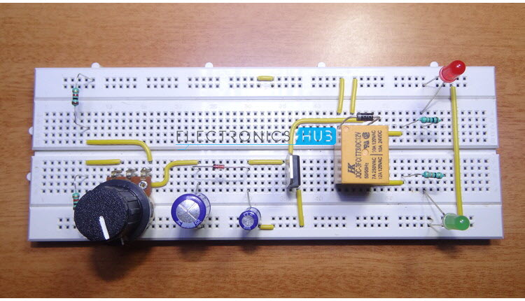
Can you please upload the circuit diagram for the bread board as the video quality is not good enough to see the exact slots where the components are to be plugged.
Hi
I am redoing a circuit controller that requires 1/2 sec to 6 seconds, what are the values with this circuit?
many thanks Steve
What is the purpose of the two 1k-ohm resisters in series with the 100k-ohm potentiometer?
Thanks in advance……Jim