Light Emitting Diodes or LEDs are the mostly commonly used components in many applications. They are made of semiconducting material. In this project, I will describe about basics of Interfacing LED with 8051 Microcontroller.
Principle behind Interfacing LED with 8051
The main principle of this circuit is to interface LEDs to the 8051 family micro controller. Commonly, used LEDs will have voltage drop of 1.7v and current of 10mA to glow at full intensity. This is applied through the output pin of the micro controller.
Circuit Diagram

NOTE: I suggest you to connect 1KΩ Pull-up resistors to all the pins of PORT0 of 8051. I haven’t shown that connection in this circuit diagram
Components Required
- AT89C51 (8051 Microcontroller)
- 8 LEDs
- 8 Resistors – 1KΩ
- Crystal oscillator – 11.0592MHz
- 2 Capacitors – 33pF
- 2 Resistors – 10KΩ
- 1 Capacitor – 10μF
- 1 Push Button
- 8051 Programmer
- 5V Power Supply
Circuit Design
The circuit mainly consists of AT89C51 microcontroller. AT89C51 belongs to the family of 8051 microcontroller. It is an 8-bit microcontroller. This microcontroller has 4KB of Flash Programmable and Erasable Read Only Memory and 128 bytes of RAM. This can be programmed and erased a maximum of 1000 times.
It has two 16 bit timers/counters. It supports USART communication protocol. It has 40 pins. There are four ports are designated as P0, P1, P2, and P3. Port P0 will not have internal pull- ups, while the other ports have internal pull-ups.
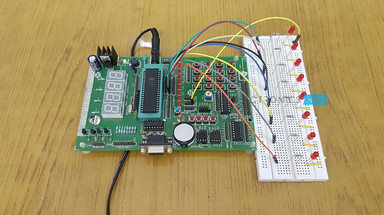
In this circuit, LEDs are connected to the port P0. The controller is connected with external crystal oscillator to pin 18 and 19 pins. Crystal pins are connected to the ground through capacitors of 33pf.
Also Try This – [Interfacing 7 Segment Display to 8051 Microcontroller]
How to Control LEDs?
Light Emitting Diodes are the semi conductor light sources. Commonly used LEDs will have a cut-off voltage of 1.7V and current of 10mA. When an LED is applied with its required voltage and current it glows with full intensity.
The Light Emitting Diode is similar to the normal PN diode but it emits energy in the form of light. The color of the emitted light depends on the band gap of the semiconductor material. The following figure shows “how an LED glows?”
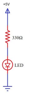
Thus, LED is connected to the AT89C51 microcontroller with the help of a current limiting resistor. Here, the resistor value is calculated by using the following formula.
R= (V-1.7)/10mA, where V is the input voltage.
Generally, microcontrollers output a maximum voltage of 5V. Thus, the value of resistor calculated for this is 330 Ohms. This resistor can be connected to either the cathode or the anode of the LED.
NOTE: I have connected 1KΩ Resistors to the LEDs.
Circuit Simulation:
How to Operate?
- Initially, burn the code into the microcontroller.
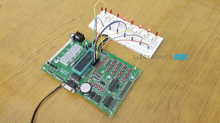
- Now, connect the LEDs to the Port0 of the microcontroller.
- Switch on the circuit.
- You can observe LEDs glowing.
- Now, switch off the circuit.
Algorithm
- Initially, include the “reg51.h” header file in your code.
- Now write a function for producing delay using for loop.
- Start the main function.
- Inside the while loop write the condition to port pin for making it logic high or low.
- Initially, make it high for some delay of 1000 microseconds.
- Now make the port pin low.
- Again give some delay of 1000 microseconds.
- Repeat this for 8 times using for loop.
- In another loop, try to represent the binary equivalent of the first 255 number using LEDs.
- Now close the while loop and also main.
Code
Logic of the Code
Here, for the first 7 seconds, the program will execute the LED Blink function i.e., all the LEDs will turn ON and OFF in the interval of 1 second. Then the program jumps to binary representation of 1 byte data using 8 LEDs. Here, for every 500 milli seconds the value will increment by 1, and when it reaches to 255 then the program will start from the beginning.
Circuit Applications
- LEDs are widely used in many applications like in seven segments.
- They are used in dot matrix displays.
- They can be used for street lights.
- They are used as indicators.
- They can be used in traffic lights.
- They are used in emergency lights
- They can used to make electronic designs.
Summary:
Interfacing LEDs with the 8051 microcontroller is a fundamental experiment that helps beginners understand how microcontrollers control external devices. By connecting LEDs to the output ports of the AT89C51 (a variant of the 8051 family), users can observe how digital signals are used to turn LEDs on and off. This exercise also involves calculating appropriate resistor values and using binary patterns to display sequences.
Have questions? Feel free to share your queries or doubts about interfacing LEDs with the 8051 in the comments section below—we’re here to help!

23 Responses
i want to take as an hobby project.
LED looks like it is interesting
Nice explanation, thanks!
is the complete developement board required for just interfacing the led’s ?
No need complete of complete board..You need only microcontroller with code burned into it,reset cirucit ,crystal,Leds
What do you know about wireless led interfacing?
i want to learn about microcontroller because i’m an student of electrical engineering.
im interested to make the same project
Great go ahead, All the best!!
Whats the crystal oscillator’s varient? The shop keeper asks for the version number
so nice..
PLS I NEED TO KNOW THE MAIN RESEARCHER OF THIS WORK AND THE YEAR IT WAS CREATED?
under what conditions will the microcontroller output 5v.
Where do we have to connect the power supply.
Hi, If you are using a development board, there will be provision to connect 12V supply through a DC Power Jack, which will be regulated to 5V. NOTE: the supply voltage for 8051 should be 5V. You can directly connect this to Pin 40.
so nice article….
Please I need a copy of the complete project report
Can I get the program for this circuit.
Hi,
Code is present in the “Download Project Code” Section. It will be downloaded in zip format.
Thanks.
I want to learn lot of uses in microcontroller.I am interested in electronics based skills.
Nice tutorial.
Ok
Nice article