Almost every mechanical movement that we see today is accomplished by an electric motor. An electric motor takes electrical energy and produces mechanical energy. Electric motors come in various ratings and sizes. Some applications of large electric motors include elevators, rolling mills and electric trains. Some applications of small electric motors are robots, automobiles and power tools. Electric motors are categorized into two types: DC (Direct Current) motors and AC (Alternating Current) motors. The function of both AC and DC motors is same i.e. to convert electrical energy to mechanical energy.
Outline
ToggleUnderstand AC and DC Electric Motors
The basic difference between these AC and DC motors is the power supply which is an AC source for AC motors and a DC source like a battery for DC motors. Both AC and DC electric motors consist of a stator which is a stationary part and a rotor which is a rotating part or armature of the motor. The principle of working of an electric motor is based on the interaction of magnetic field produced by the stator and the electric current flowing in the rotor in order to produce rotational speed and torque.
What Is A DC Motor?
A DC electric motor is a machine that converts direct current (DC) electrical energy into mechanical energy. In simpler terms, it uses electricity from a battery or similar DC source to produce rotation.
DC motor is an electromechanical actuator used for producing continuous movement with controllable speed of rotation. DC motors are ideal for use in applications where speed control and servo type control or positioning is required. There are different kinds of DC motors and they all work on the same principle.
A simple DC motor is shown below.
As mentioned earlier, any motor consists of two parts viz. stator and rotor. Based on the configuration and construction, there are three types of DC motors: brushed motor, brushless motor and servo motor.
Working Principle of DC Motor
An electromechanical energy conversion device will take electrical energy at the input and produces a mechanical energy at the output side. There are three electrical machines that are extensively used for this task: a DC motor, an induction or asynchronous motor and a synchronous motor. Induction motor and synchronous motors are AC motors. In all the motors, the electrical energy is converted into mechanical when the magnetic flux linking a coil is changed.
An electric motor takes electrical energy as input and converts into mechanical energy.
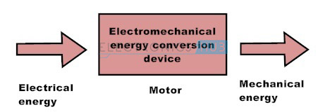
When the electrical energy is applied to a conductor which is placed perpendicular to the direction of the magnetic field, the result of the interaction between the electric current flowing through the conductor and the magnetic field is a force. This force pushes the conductor in the direction perpendicular to both current and the magnetic field, hence, the force is mechanical in nature.
The value of the force can be calculated if the density of the magnetic field B, length of the conductor L and the current flowing in the conductor I are known.
The force exerted on the conductor is given by
F = B×I×L Newtons
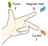
The direction of the motion of the conductor can be determined with the help of Fleming’s Left Hand Rule.
Fleming’s Left Hand Rule is applicable to all electric motors.
The figure representing Fleming’s Left Hand Rule is shown below.
When a conductor which is carrying current is placed in a magnetic field, a force acts on the conductor that is perpendicular to both the directions of magnetic field and the current.
According to Fleming’s Left Hand Rule, the left hand thumb represents the direction of the force, the index finger represents the direction of the magnetic field and the middle finger represents the direction of the current.
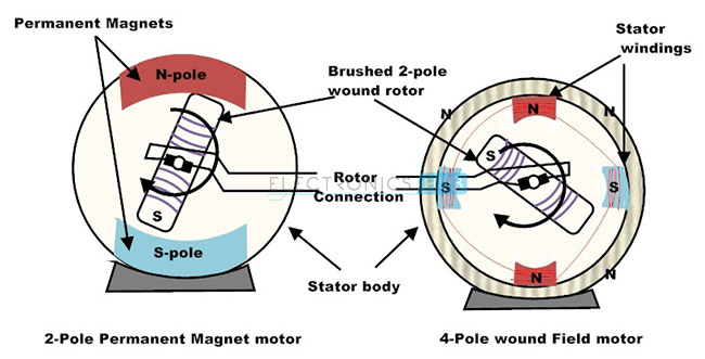
A DC motor consists of two sets of coils called armature winding and field winding. Field winding is used to produce the magnetic field. A set of permanent magnets can also be used for this purpose. If field windings are used, it is an electromagnet. The field winding is the fixed part of the motor or a stator. The armature winding is rotor part of the motor. The rotor is placed inside of stator. The rotor or the armature is connected to the external circuit through a mechanical commutator.
Generally, Ferro magnetic materials are used to make both stator and rotor which are separated by air gap. The coil windings inside the stator are made of series or parallel connections of number of coils. The Copper windings are generally employed for both armature and field windings.
The principle of operation of a DC motor is explained below.
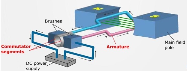
Consider a coil placed in a magnetic field with a flux density of B Tesla. When the coil is supplied with direct current by connecting it to a DC supply, a current I flows through the length of the coil. The electric current in the coil interacts with the magnetic field and the result is exertion of a force on the coil according to the Lorenz force equation. The force is proportional to the strength of the magnetic field and the current in the conductor.
The same principle is used in DC motor and it consists of several coils that are wound on the armature and all the coils experience the same force. The result of this force is the rotation of the armature. The rotation of the conductor in the magnetic field will result in torque. The magnetic flux linking with the conductor is different at different positions of the coil in the magnetic field and these causes to induce an emf in the coil according to the Faradays laws of electromagnetic induction. This emf is referred to as back emf. The direction of this emf is opposite to the supply voltage which is responsible for current to flow in the conductor. Hence the total amount of current flowing in the armature is proportional to the difference between the supply voltage and the back emf.
The electrical equivalent of a DC motor is shown below.

A DC motor electrical equivalent circuit is divided into two circuits: field circuit and armature circuit. Field circuit is responsible for the magnetic field and is supplied with a separate DC voltage Vf. The resistance and inductance of the field winding are represented by Rf and Lf. As a result of the voltage, a current If is produced in the winding and it establishes the necessary magnetic field.
In the armature, a voltage VT is applied across the terminals of the motor and a current Ia flows in the armature circuit. The resistance of the armature winding is Ra and the total voltage induced in the armature is Eb.
Applying Kirchhoff’s Voltage Law in both the circuits,
Vf = If * Rf
VT = Ia * Ra + Eb
The torque developed in the motor is
T = K * Ia * Φ
Where k is constant depending on coil geometry and Φ is magnetic flux.
The electrical power of the motor is Eb * Ia.
The developed power which is the power converted to mechanical form is given below:
P = T * ωn where ω is the angular speed.
This is the total power that is delivered to the induced armature voltage and
Eb * Ia = T * ωn
Types of DC Motors
DC motors are mainly classified into two types in the way of rotor is powered. They are Brushed DC motors and Brushless DC motors. As its name indicates, the brushes are present in brushed DC motor to supply the current to the rotating armature via the commutator whereas in a brushless DC motor no need of brushes as it uses a permanent magnet rotor.
Brushed DC Motor
In this type of motors, magnetic field is produced by passing current through a commutator and brush which are inside the rotor. Hence, they are called Brushed Motors. The brushes are made up of carbon. These can be separately excited or self-excited motors.
The stator part of the motor consists of coils connected in a circular fashion in such a way that the required alternative north and south poles are formed. This coil setup can be in series or in parallel to the rotor coil winding forming series wound DC motors and shunt wound DC motors. The armature or the rotor part of the DC motor consists of Commutator which essentially a current carrying conductor connected at one end to copper segments which are electrically isolated. External power can be connected to commutator via the brushes as the armature rotates.
Brushed DC Motor Types
DC motors are classified according to the electrical connections of armature winding and the field winding. Different types of connections give rise to different types of motors. DC motors are divided based on the generation of magnetic field. There are three main types of DC motors: Separately Excited, Self-Excited and Permanent Magnet. In case of permanent magnet type motors, a powerful magnet is used to generate the required magnetic field. In case of separately excited and self-excited motors, an electromagnet is deployed in the stator structure.
The self-excited type DC motors are again divided into three types: Shunt Excited, Series Excited and Compound Excited.
Compound Excited type motors are further divided into Cumulative Compound and Differential Compound with Long Shunt and Short Shunt types in each of the Compound Excited.
Separately Excited Motors
As the name suggests, a separately excited DC motor uses separate supplies for armature winding and field winding. This means that the armature winding and field winding are electrically separate from each other.
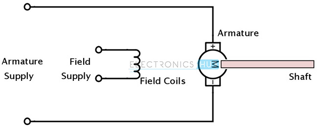
The armature current and the field current do not interfere with each other as the sources are different. But the total input power is the sum of individual powers. If Vf and If are voltage and current corresponding to the magnetic field circuit and Vt and Ia are voltage and current corresponding to armature circuit, then the total input power is given by Vf * If + Vt * Ia.
Self-Excited Motors
In self-excited DC motors, instead of separate voltage sources, the field winding and armature winding are connected across the single supply source. This connection can be made in two ways: shunt or parallel and series. Hence, self-excited motors are again classified into Shunt Wound DC motors and Series Wound DC motors.
Shunt DC Motors: In case of shunt DC motors, the field winding and armature winding are connected in parallel across the same supply and hence the field windings are exposed to entire terminal voltage. Even though the supply is same, the field current and armature current are different. The speed of a shunt DC motor is constant and doesn’t vary with mechanical load at the output.
The structure of shunt DC motor is shown below.
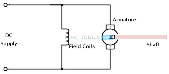
The electrical equivalent of Shunt DC motor is shown below.
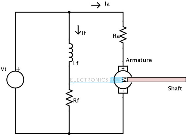
If Eb is the back emf of the motor, then
Vt = Eb + Ia * Ra
If the armature constant is Ka and the speed of its rotation is ω, then
Eb = Ka * ω * Φ
Where Φ is the magnetic flux.
Hence,
Vt = Ka * ω * Φ + Ia * Ra
The total current is It = If + Ia
Therefore the total power is P = Vt * It
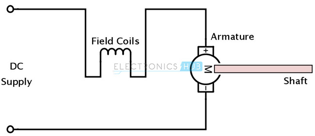
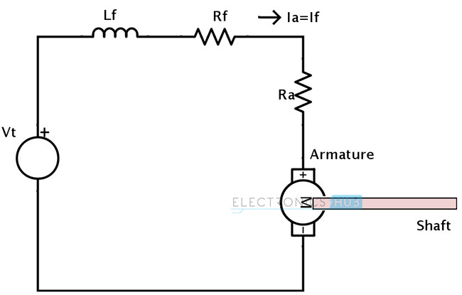
Series Motors: In case of series DC motors, the field winding and armature windings are connected in series with the power supply. Hence same current flows in the field winding and armature winding.
A series wound motor is also called Universal motor as it works with either an AC voltage supply or a DC voltage supply.
A series wound motor will always rotate in the same direction regardless of the polarity of the voltage source. This is because if we change the polarities, the polarity of the armature winding and the direction of the magnetic field are reversed simultaneously. The speed of the series DC motor varies with mechanical load.
The diagrammatic representation of a series wound DC motor is shown below.
The electrical equivalent of a series DC motor is shown below.
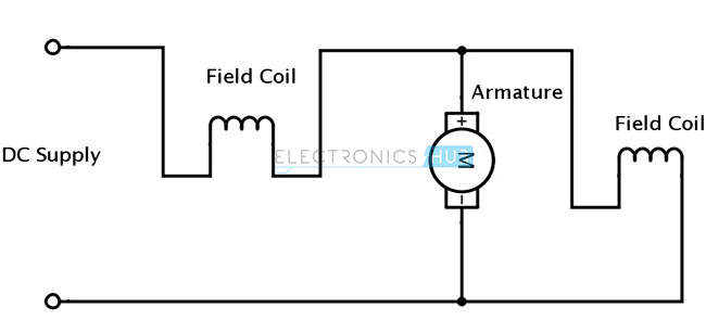
Compound Motors: Compound wound motors use the combination of both series windings and shunt field windings. The series winding is connected in series with the armature of the motor while the shunt winding is connected in parallel.
Since there are two field circuits that are producing magnetic fields, compound DC motors can be further divided into two types based on the orientation of the flux. Those are Cumulative Compound DC motors and Differential Compound DC motors.
If the flux of shunt field assists the flux of series field i.e. both are in same direction, then it is a cumulative compound DC motor. In this case, the total magnetic flux is the sum of individual fluxes.
ΦTOTAL = ΦSERIES + ΦSHUNT
Structure of a cumulative compound DC motors is in the following figure.
The electrical equivalent is shown below.
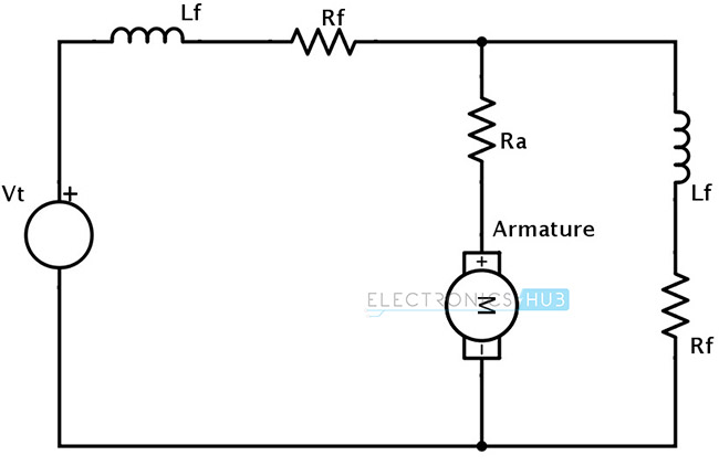
In case of differential compound DC motors, the flux produced by series field and shunt field are in opposite direction and the total flux is the difference between them.
ΦTOTAL = ΦSERIES – ΦSHUNT
In this case, the net flux is less than the original flux and hence differential compound DC motors do not find many practical applications.
Both cumulative and differential compound DC motors can be further divided into long shunt and short shunt devices based on the shunting of the shunt field winding.
If case of long shunt motors, the shunt field winding is parallel to both the armature and the series field winding.
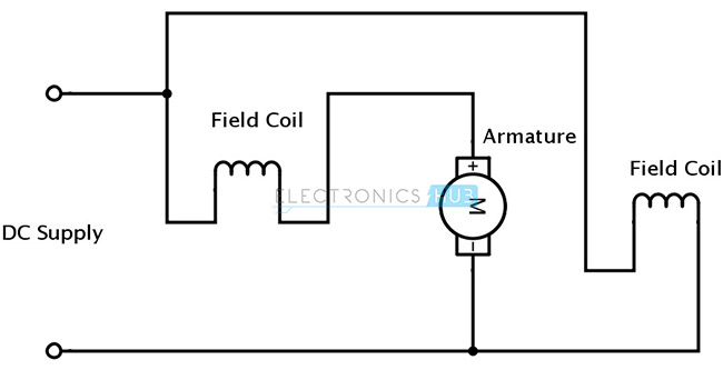
If the shunt field winding is parallel to only the armature, then it is short shunt.
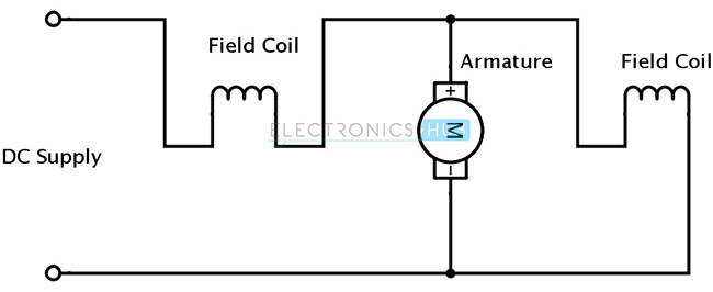
Permanent Magnet DC Motors: In case of permanent magnet DC motors, a powerful magnet is used to produce the magnetic field. Hence a permanent magnet DC motor consists of only armature winding.
A permanent magnet brushed DC motor is shown below.
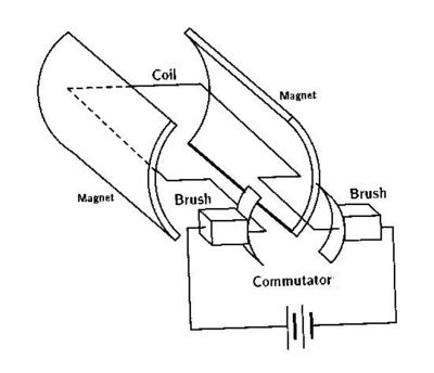
Permanent magnet brushed DC motors are smaller and cheaper than stator wound type DC motors. Generally rare earth magnets like Samarium Cobalt or Neodymium Iron Boron are used as magnets in permanent magnet DC motors as they are very powerful magnets and have high magnetic fields.
The speed/torque characteristics of a permanent magnet DC motor are more linear than stator wound DC motors.
The disadvantage of a brushed DC motor is the occurrence of sparks between commutator and brushes under heavy load conditions. This generates large amount of heat and reduces the lifetime of the motor.
Brushless DC Motor
Brushless DC motors typically consist of a permanent magnet rotor and a coil wound stator. This design by using permanent magnets in rotor eliminates the need for brushes in the rotor part. Hence, in contrast to brushed DC motors, these type do not contain any brushes and therefore no wear and tear of brushes as little amount of heat is generated.
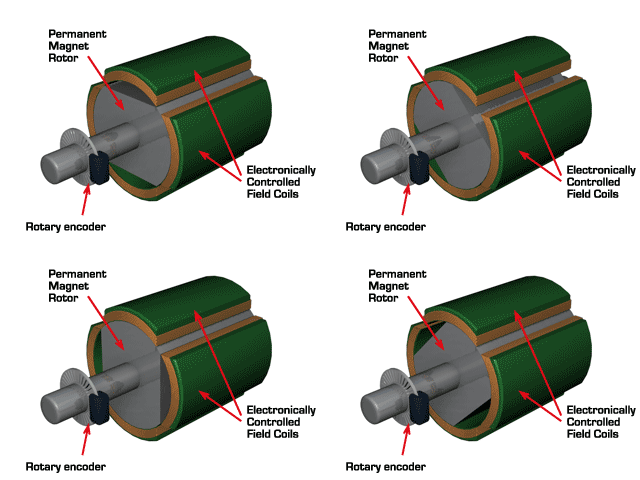
As there are no brushes in the motor, there should be some other means to detect the angular position of the rotor. Hall Effect sensors are used to produce the feedback signals that are required to control any semiconductor switching devices. Brushless DC motors are more expensive than brushed DC motors and are more efficient than their brushed cousins.
DC Servo Motor
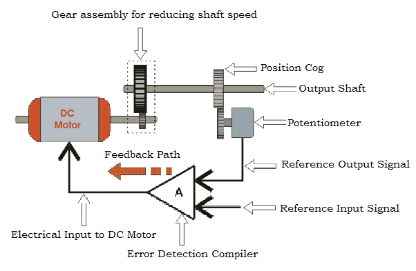
A small DC motor will rotate at high speed, but its torque is insufficient to move any load. A DC servo motor consists of four parts: a normal DC motor, a gearbox for speed control, a control circuit and a position sensing unit. The gearbox will take the high speed input and converts into a slower but more practical speed. The position sensing unit is generally a potentiometer. The control circuit is an error detector amplifier.
In DC servo motors, the position of the shaft is feedback to a control circuit and therefore, they are used in closed loop applications.
The potentiometer is connected to the shaft. It allows the control circuit to monitor the position of the motor. This position is compared with a reference input signal by the control circuit. The output of the control circuit is feedback to the motor. If there is any mismatch in the current position and the reference position, an error signal is generated at the output of the error detecting amplifier. Based on this signal, the shaft rotates and goes to the required location and stops.
Most DC servo motors can rotate up to 1800 in either direction. DC servo motors are used in remote controlled devices, robotics and even in large industrial applications.
Driving a DC Motor
A DC motor can be switched ON or OFF with the help of transistors, switches or relays. The simplest form of motor control is linear control which uses a bipolar junction transistor acting as a switch. The purpose of drive circuits is to control the current in the windings. The speed of the motor can be controlled by varying the amount of base current in the transistor. If the transistor is in active state, then the motor rotates with half speed as only half of the supply voltage goes to the motor. The motor rotates at its maximum speed when all of the supply voltage goes to it. This happens when the transistor is in saturation.
The following circuit is used for driving a motor in one direction.
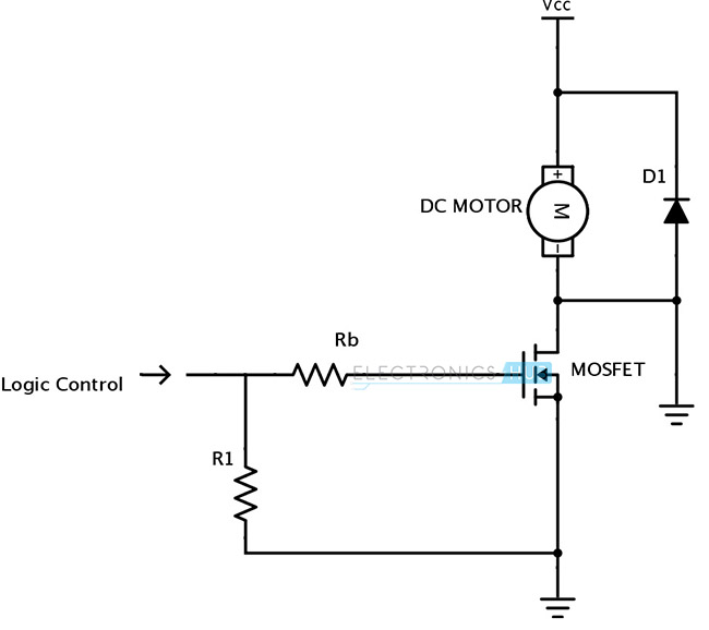
In the above circuit, the resistors Rb and R1 are very important. The resistor Rb is used to protect the control circuit from current spikes. The resistor R1 ensures that the transistor is turned OFF when the input pin is tri-stated.
The speed of the motor can be controlled by modulating the supply voltage as the speed is proportional to the mean value of the supply.
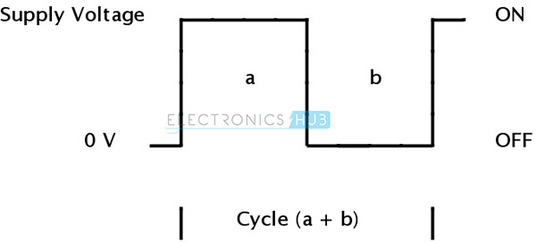
The percentage of ON time is called as Duty cycle. The duty cycle for above pulse is given as β = a / (a + b).
By varying the duty cycle, i.e. by varying the width of the pulse, the rotational speed of the motor can be varied. This is called as PWM (Pulse Width Modulation) technique. The speed can also be varied without varying the width of the pulse. This is achieved by varying the frequency of the pulse. This is called PFM (Pulse Frequency Modulation).
Changing the Direction of DC Motor: The disadvantage of above mentioned driving circuit is that it is uni – directional, i.e. the motor always rotates in a single direction. In order to change the direction of rotation of the motor, the polarity of the supply must be reversed. To achieve this, different switches can be used.
The first connection is using a DPDT (double pole, double throw) switch.
The connection is shown below.
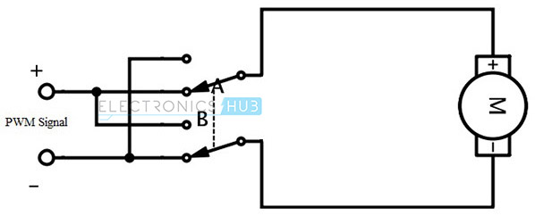
When the switch is in position A, the motor rotates in forward direction. When the terminals of the motor are connected to the switch in position B, the direction reverses.
The second connection is using four SPST (Single Post, Single Throw) switches.
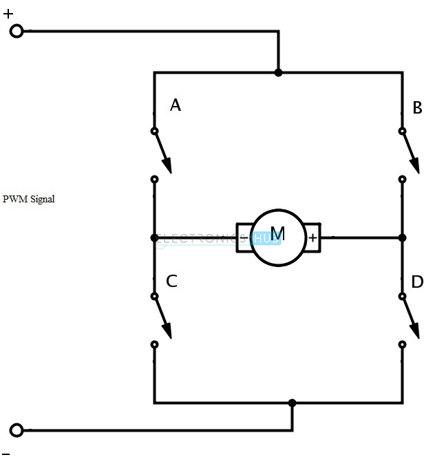
By combination of different switches, different functionalities can be achieved.
The combinations and their respective operations are as follows.
A + D — Forward Direction
B + C — Reverse Direction
A + B — Stop and Brake
C + D — Stop and Brake
All OFF — Stopped
H – Bridge Motor Driver
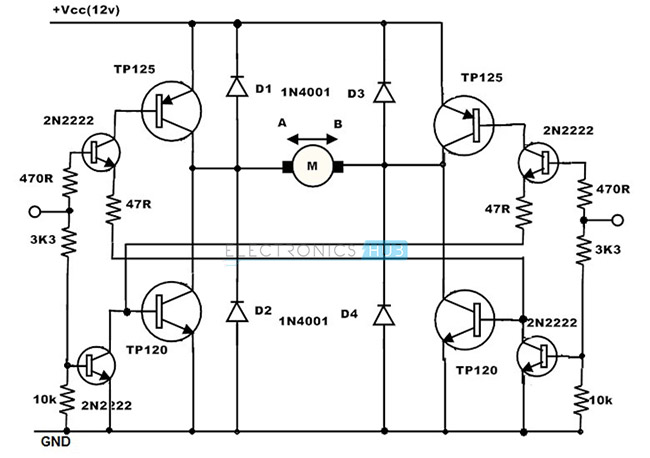
In order to achieve a better bi – directional control of a DC motor, a circuit called an H – bridge is required. The name H – bridge is given for its schematic appearance with respect to the position of the motor on the center bar. This circuit can be used to move current in either direction through the windings of a motor.
The circuit of an H – bridge DC motor driver is shown below.
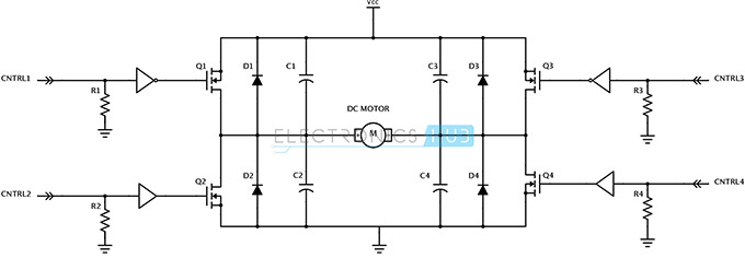
The control signal CNTRL 1, CNTRL 2, CNTRL 3 and CNTRL 4 are used to switch ON and OFF the transistors Q1, Q2, Q3 and Q4 respectively.
The operation is self-explanatory. One important consideration that must be taken into account is that all the FETs must be in OFF state when the inputs are unpredictable, so that the transistors on each half of the H-Bridge will not turn on at the same time. Hence, the pull down resistor for each transistor is used.
Another circuit for H – Bridge implementation is shown below.
L293D Motor Driver IC
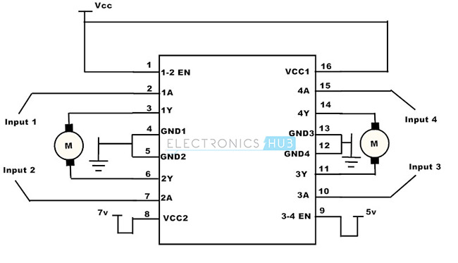
L293D IC is a motor driver IC that works on the concept of H – bridge. This IC allows the motor to drive in both the directions. L293D IC is a 16 pin device with two sets of inputs and outputs. Hence it is possible to control two DC motors with a single IC.
The pin diagram of L293D IC is as below.
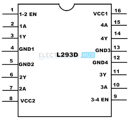
For motor 1,
Pin 2 = logic 1 and pin 7 = logic 0 —- forward direction
Pin 2 = logic 0 and pin 7 = logic 1 —- reverse direction
For other combinations, there is no rotation.
Similarly for motor 2,
Pin 10 = logic 1 and pin 15 = logic 0 —–forward direction
Pin 10 = logic 0 and pin 15 = logic 1 —–reverse direction.
The circuit for controlling two motors using L293D motor driver IC is shown below.





One Response
It’s through and I like it